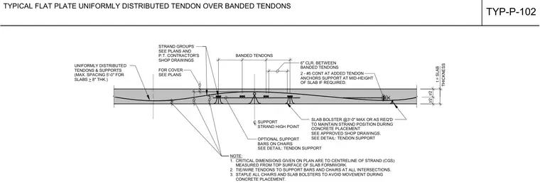
Post-tensioned flat plate concrete slab detailing the arrangement of uniformly distributed tendons placed over banded tendon groups. The assembly includes strand supports, slab bolsters spaced at a maximum of three feet, and optional support bars on chairs to maintain proper strand positioning during concrete placement. Two continuous number five reinforcing bars are provided at added tendon anchors for support at the mid-height of the slab when required. Critical dimensions are measured from the top surface of the slab formwork to the centreline of strand, with a six-inch clear spacing maintained between banded tendons. All tendons are tied to support bars and chairs at intersections, and slab bolsters are stapled to prevent movement during placement.
NOTE: 1. CRITICAL DIMENSIONS GIVEN ON PLAN ARE TO CENTRELINE OF STRAND (CGS) MEASURED FROM TOP SURFACE OF SLAB FORMWORK. 2. TIE/WIRE TENDONS TO SUPPORT BARS AND CHAIRS AT ALL INTERSECTIONS. 3. STAPLE ALL CHAIRS AND SLAB BOLSTERS TO AVOID MOVEMENT DURING CONCRETE PLACEMENT. UNIFORMLY DISTRIBUTED TENDONS & SUPPORTS (MAX. SPACING 5'-0" FOR SLABS > 8" THK.) STRAND GROUPS SEE PLANS AND P.T. CONTRACTOR'S SHOP DRAWINGS OPTIONAL SUPPORT BARS ON CHAIRS SEE DETAIL: TENDON SUPPORT SUPPORT STRAND HIGH POINT SLAB BOLSTER @3'-0" MAX OR AS REQ'D TO MAINTAIN STRAND POSITION DURING CONCRETE PLACEMENT SEE APPROVED SHOP DRAWINGS. SEE DETAIL: TENDON SUPPORT 2 - #5 CONT AT ADDED TENDON ANCHORS SUPPORT AT MID-HEIGHT OF SLAB IF REQUIRED. 6" CLR. BETWEEN BANDED TENDONS FOR COVER SEE PLANS BANDED TENDONS C L t/2 t/2 t = SLAB TYP-P-102 TYPICAL FLAT PLATE UNIFORMLY DISTRIBUTED TENDON OVER BANDED TENDONS THICKNESS
Members view this detail in full resolution, download the CAD files (SVG, PDF), and can adapt it in the built-in CAD editor — export DXF, DWG, or PDF.
Start membership