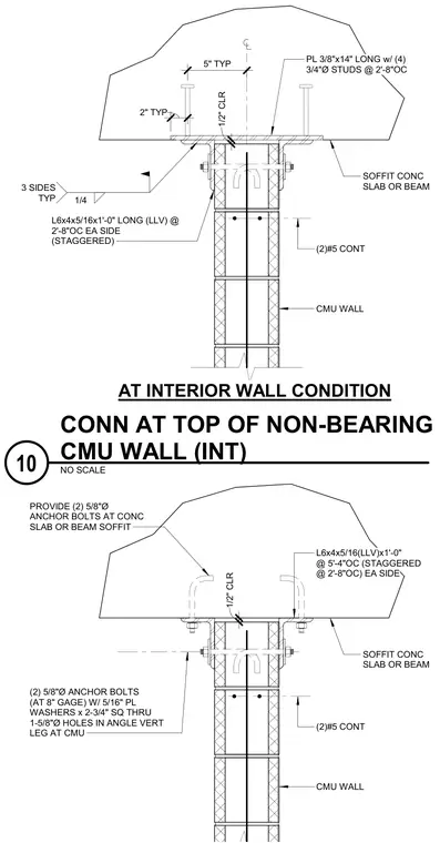
An interior non-bearing concrete masonry unit wall connects structurally at the top to an overhead concrete slab or beam. The assembly provides lateral bracing while allowing for deflection through a one-half-inch clearance maintained at the top of the wall. Two alternative attachment configurations are provided: one utilizing an embedded three-eighths-inch by fourteen-inch plate with four three-quarter-inch diameter studs welded to structural angles, and another utilizing two five-eighths-inch diameter anchor bolts embedded directly into the concrete soffit. Staggered L6x4x5/16 structural steel angles measuring one foot long are placed on each side of the wall at two-foot eight-inch or five-foot four-inch on-center spacings. Two five-eighths-inch diameter anchor bolts with five-sixteenths-inch plate washers measuring two and three-quarters square pass through one and five-eighths-inch diameter holes in the vertical leg of the angle at the concrete masonry unit. Continuous number five reinforcing bars are incorporated within the top of the wall for structural integrity.
SOFFIT CONC SLAB OR BEAM (2)#5 CONT L6x4x5/16(LLV)x1'-0" @ 5'-4"OC (STAGGERED @ 2'-8"OC) EA SIDE CMU WALL PROVIDE (2) 5/8"Ø ANCHOR BOLTS AT CONC SLAB OR BEAM SOFFIT (2) 5/8"Ø ANCHOR BOLTS (AT 8" GAGE) W/ 5/16" PL WASHERS x 2-3/4" SQ THRU 1-5/8"Ø HOLES IN ANGLE VERT LEG AT CMU 1/2" CLR AT INTERIOR WALL CONDITION SOFFIT CONC SLAB OR BEAM PL 3/8"x14" LONG w/ (4) 3/4"Ø STUDS @ 2'-8"OC CMU WALL L6x4x5/16x1'-0" LONG (LLV) @ 2'-8"OC EA SIDE (STAGGERED) 5" TYP 2" TYP 1/4 3 SIDES TYP (2)#5 CONT 1/2" CLR NO SCALE CONN AT TOP OF NON-BEARING CMU WALL (INT) 10
Members view this detail in full resolution, download the CAD files (SVG, PDF), and can adapt it in the built-in CAD editor — export DXF, DWG, or PDF.
Start membership