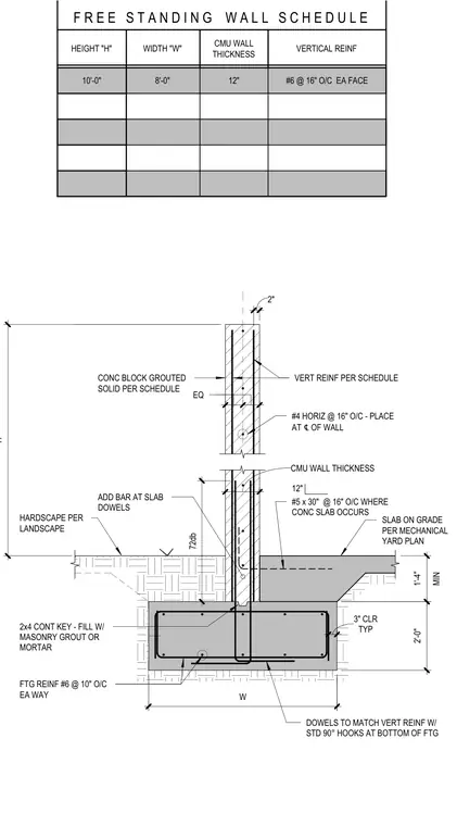
This drawing provides a schedule and section detail for a free-standing masonry wall supported by a reinforced concrete footing. The concrete masonry unit wall is twelve inches thick and is grouted solid per the schedule, with vertical reinforcement of number six bars at sixteen inches on center on each face. Horizontal reinforcement consists of number four bars at sixteen inches on center placed at the centerline of the wall. The concrete footing is two feet deep by width 'W' and is reinforced with number six bars at ten inches on center each way. Where a concrete slab occurs, number five by thirty inch dowels are placed at sixteen inches on center with standard ninety degree hooks at the bottom of the footing. A continuous two by four key is filled with masonry grout or mortar at the footing interface. Hardscape and slab on grade conditions are coordinated per landscape and mechanical yard plans.
HEIGHT "H" WIDTH "W" CMU WALL THICKNESS VERTICAL REINF F R E E S T A N D I N G W A L L S C H E D U L E 10'-0" #5 x 30" @ 16" O/C WHERE CONC SLAB OCCURS DOWELS TO MATCH VERT REINF W/ STD 90° HOOKS AT BOTTOM OF FTG VERT REINF PER SCHEDULE CONC BLOCK GROUTED SOLID PER SCHEDULE 12" #4 HORIZ @ 16" O/C - PLACE AT ℄ OF WALL EQ ADD BAR AT SLAB DOWELS SLAB ON GRADE PER MECHANICAL YARD PLAN 2x4 CONT KEY - FILL W/ MASONRY GROUT OR MORTAR FTG REINF #6 @ 10" O/C EA WAY 2'-0" H 2" W 72db MIN 1'-4" TYP 3" CLR CMU WALL THICKNESS #6 @ 16" O/C EA FACE 8'-0" 12" HARDSCAPE PER LANDSCAPE
Members view this detail in full resolution, download the CAD files (SVG, PDF), and can adapt it in the built-in CAD editor — export DXF, DWG, or PDF.
Start membership