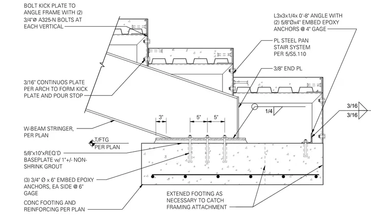
A steel stair stringer base connection is anchored to a concrete footing. A wide-flange beam stringer bears on a five-eighth-inch by ten-inch base plate set over approximately one inch of non-shrink grout. The base plate is secured with three three-quarter-inch diameter by six-inch embedded epoxy anchors on each side at a six-inch gauge. The concrete footing and reinforcing are sized per plan, with extended footing as necessary to catch framing attachment. A three-eighth-inch end plate connects to the steel pan stair system. An L3x3x1/4 angle with two five-eighth-inch diameter by four-inch embedded epoxy anchors at a four-inch gauge is provided alongside a three-sixteenth-inch continuous plate forming a kick plate and pour stop, bolted with two three-quarter-inch diameter A325-N bolts at each vertical.
1/4 W-BEAM STRINGER, PER PLAN (3) 3/4" Ø x 6" EMBED EPOXY ANCHORS, EA SIDE @ 6" GAGE 5/8"x10"xREQ'D BASEPLATE w/ 1"+/- NON- SHRINK GROUT 3/8" END PL PL STEEL PAN STAIR SYSTEM PER 5/S5.110 5" 5" 3" 3/16" CONTINUOS PLATE PER ARCH TO FORM KICK PLATE AND POUR STOP BOLT KICK PLATE TO ANGLE FRAME WITH (2) 3/4" ⌀ A325-N BOLTS AT EACH VERTICAL EXTENED FOOTING AS NECESSARY TO CATCH FRAMING ATTACHMENT CONC FOOTING AND REINFORCING PER PLAN T/FTG PER PLAN 3/16 3/16 L3x3x1/4x 0'-8" ANGLE WITH (2) 5/8"Øx4" EMBED EPOXY ANCHORS @ 4" GAGE
Members view this detail in full resolution, download the CAD files (SVG, PDF), and can adapt it in the built-in CAD editor — export DXF, DWG, or PDF.
Start membership