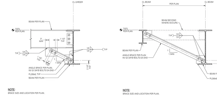
An angle brace per plan connects the structural steel beam and column or girder web using two 3/4-inch diameter bolts at each end in this beam flange brace connection for beams oriented perpendicular to a supporting girder or beam. A 3/8-inch by 6-inch typical plate is welded to the members with typical one-quarter-inch fillet welds. Brace sizes and locations are specified per plan.
BEAM PER PLAN ANGLE BRACE PER PLAN W/ (2) 3/4"Ø BOLTS EA END CL BEAM CL BEAM PER PLAN BEAM PER PLAN 1/4 1/4 TYP PL3/8x6, TYP T/STL PER PLAN 2 1/2" 1 1 MIN NOTE: BRACE SIZE AND LOCATION PER PLAN. BEAM BEYOND WHERE OCCURS CL GIRDER ANGLE BRACE PER PLAN, W/ (2) 3/4"Ø BOLTS EA END 1/4 1/4 TYP T/STL PER PLAN BEAM PER PLAN PL3/8x6, TYP MIN 3" TYP 1 1/2" 1/4 1/4 TYP TYP 1 1/2" TYP 3" TYP 2 1/2" 1 1 MIN NOTE: BRACE SIZE AND LOCATION PER PLAN. BEAM PER PLAN I $ ©' ------- s r F ic. 0 j 0 <> IF 0 \c <'/fy<' <■ 11 < K4 ^.h
Members view this detail in full resolution, download the CAD files (SVG, PDF), and can adapt it in the built-in CAD editor — export DXF, DWG, or PDF.
Start membership