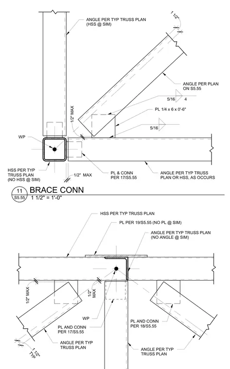
A structural steel truss bracing connection utilizes hollow structural section members, gusset plates, and welded angle profiles. The assembly incorporates a quarter-inch by six-inch by zero-foot-six-inch steel plate connected with five-sixteenth-inch fillet welds. Specific angles and plates are sized per the typical truss plan or referenced details S5.55. Work points and maximum clearances of one-half inch are designated for structural alignment.
1 1/2" 1/2" MAX WP ANGLE PER TYP TRUSS PLAN (HSS @ SIM) ANGLE PER PLAN ON S5.55 HSS PER TYP TRUSS PLAN (NO HSS @ SIM) PL & CONN PER 17/S5.55 ANGLE PER TYP TRUSS PLAN OR HSS, AS OCCURS PL 1/4 x 6 x 0'-6" 5/16 5/16 4 1/2" MAX HSS PER TYP TRUSS PLAN PL PER 19/S5.55 (NO PL @ SIM) ANGLE PER TYP TRUSS PLAN (NO ANGLE @ SIM) WP MAX 1/2" ANGLE PER TYP TRUSS PLAN PL AND CONN PER 17/S5.55 PL AND CONN PER 18/S5.55 ANGLE PER TYP TRUSS PLAN TYP 1 1/2" 1/2" MAX 1 1/2" = 1'-0" S5.55 11 BRACE CONN
Members view this detail in full resolution, download the CAD files (SVG, PDF), and can adapt it in the built-in CAD editor — export DXF, DWG, or PDF.
Start membership