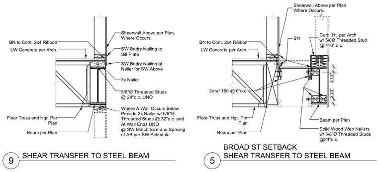
Shear transfers from a shearwall above to a supporting steel beam assembly with lightweight concrete topping per architectural plans. The connection incorporates a continuous 2x4 ribbon, a 3x nailer secured with five-eighths inch diameter threaded studs spaced at twenty-four inches on center, and specified boundary nailing. Floor trusses and hangers are provided per plan framing, bearing on the supporting steel beam. Solid wood web nailers with threaded studs at twenty-four inches on center accommodate the curb and edge conditions at the setback.
5 9 SHEAR TRANSFER TO STEEL BEAM Floor Truss and Hgr. Per Plan Beam per Plan Shearwall Above per Plan, Where Occurs. BN to Cont. 2x4 Ribbon SW Bndry Nailing at Nailer for SW Above SW Bndry Nailing to Sill Plate LW Concrete per Arch. 3x Nailer 5/8"Ø Threaded Studs @ 24"o.c. UNO BROAD ST SETBACK SHEAR TRANSFER TO STEEL BEAM Floor Truss and Hgr. Per Plan Beam per Plan BN to Cont. 2x4 Ribbon LW Concrete per Arch. Shearwall Above per Plan, Where Occurs. BN Beam per Plan Solid Wood Web Nailers w/ 5/8"Ø Threaded Studs @24"o.c. Curb, Ht. per Arch w/ 5/8Ø Threaded Stud @ 4'-0" o.c. 2 1/2" 2 3/8" 2x w/ 16d @ 6"o.c. Where A Wall Occurs Below Provide 3x Nailer w/ 5/8"Ø Threaded Studs @ 32"o.c. and At Wall Ends UNO @ SW Match Size and Spacing of AB per SW Schedule
Members view this detail in full resolution, download the CAD files (SVG, PDF), and can adapt it in the built-in CAD editor — export DXF, DWG, or PDF.
Start membership