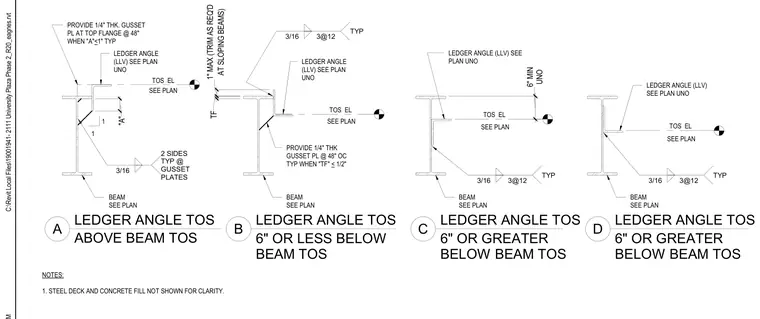
These details show ledger angle connections attached to structural steel beams at four distinct relative elevations: ledger angle top of steel above beam top of steel, six inches or less below beam top of steel, and two variations six inches or greater below beam top of steel. The ledger angle is welded to the beam web or flange with three-sixteenths inch welds spaced at twelve inches typically unless noted otherwise. When the top flange thickness is less than or equal to one-half inch, or when dimension A is one inch or less, a one-quarter inch thick gusset plate is provided at forty-eight inches on center, welded two sides with three-sixteenths inch welds. Steel deck and concrete fill are omitted for clarity.
1 1 6" OR LESS BELOW BEAM TOS LEDGER ANGLE TOS LEDGER ANGLE TOS A B LEDGER ANGLE TOS LEDGER ANGLE TOS 6" OR GREATER BELOW BEAM TOS C D SEE PLAN TOS EL PROVIDE 1/4" THK GUSSET PL @ 48" OC TYP WHEN "TF" < 1/2" SEE PLAN TOS EL LEDGER ANGLE (LLV) SEE PLAN UNO PROVIDE 1/4" THK. GUSSET PL AT TOP FLANGE @ 48" WHEN "A"<1" TYP TOS EL SEE PLAN TOS EL SEE PLAN NOTES: 1. STEEL DECK AND CONCRETE FILL NOT SHOWN FOR CLARITY. LEDGER ANGLE (LLV) SEE PLAN UNO BEAM SEE PLAN LEDGER ANGLE (LLV) SEE PLAN UNO LEDGER ANGLE (LLV) SEE PLAN UNO BEAM SEE PLAN BEAM SEE PLAN BEAM SEE PLAN 6" OR GREATER BELOW BEAM TOS TF AT SLOPING BEAMS) 1" MAX (TRIM AS REQ'D UNO 6" MIN ABOVE BEAM TOS "A" 3/16 2 SIDES TYP @ GUSSET PLATES 3/16 3@12 TYP 3/16 3@12 TYP 3/16 3@12 TYP C:\Revit Local Files\19001941- 2111 University Plaza Phase 2_R20_eagnes.rvt
Members view this detail in full resolution, download the CAD files (SVG, PDF), and can adapt it in the built-in CAD editor — export DXF, DWG, or PDF.
Start membership