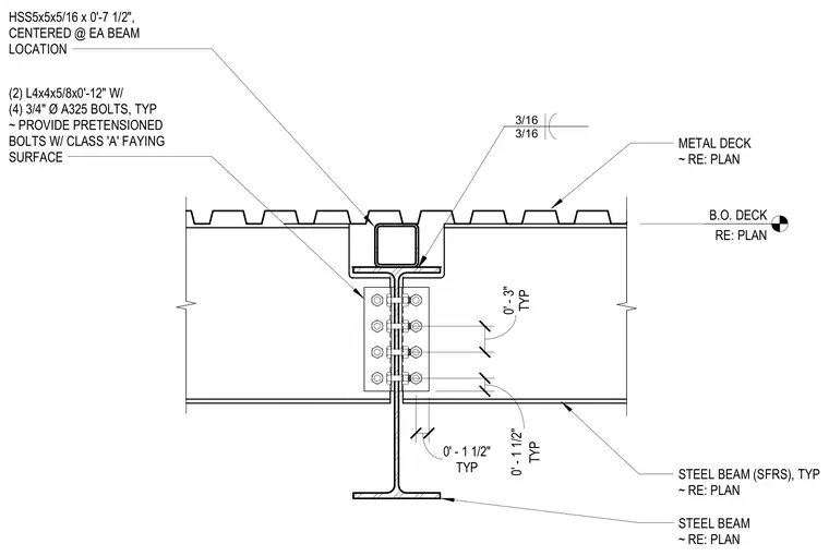
A steel collector beam connects to a supporting girder web using two L4x4x5/8 by twelve-inch angles secured with four three-quarter-inch diameter A325 bolts on each side, using pretensioned bolts with a Class A faying surface. An HSS5x5x5/16 by seven-and-a-half-inch hollow structural section is centered at the beam location above the top flange and below the metal deck, welded with three-sixteenth-inch fillet welds. The metal deck bears across the assembly with bottom of deck elevations sized per plan. The steel beam serves as part of the seismic force-resisting system.
STEEL BEAM ~ RE: PLAN STEEL BEAM (SFRS), TYP ~ RE: PLAN METAL DECK ~ RE: PLAN B.O. DECK RE: PLAN (2) L4x4x5/8x0'-12" W/ (4) 3/4" Ø A325 BOLTS, TYP ~ PROVIDE PRETENSIONED BOLTS W/ CLASS 'A' FAYING SURFACE TYP 0' - 3" TYP 0' - 1 1/2" TYP 0' - 1 1/2" HSS5x5x5/16 x 0'-7 1/2", CENTERED @ EA BEAM LOCATION 3/16 3/16
Members view this detail in full resolution, download the CAD files (SVG, PDF), and can adapt it in the built-in CAD editor — export DXF, DWG, or PDF.
Start membership