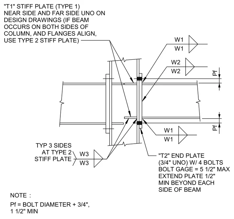
Steel beams connect to a column flange using an end plate secured with four bolts at a maximum five-and-a-half-inch bolt gauge. Type 1 stiffener plates are placed near side and far side on design drawings unless opposing beams align, in which case a Type 2 stiffener plate is used. The end plate extends a minimum of one-half inch beyond each side of the beam. A formula defines Pf as bolt diameter plus three-quarters of an inch with a one-and-a-half-inch minimum.
"T1" STIFF PLATE (TYPE 1) NEAR SIDE AND FAR SIDE UNO ON DESIGN DRAWINGS (IF BEAM OCCURS ON BOTH SIDES OF COLUMN, AND FLANGES ALIGN, USE TYPE 2 STIFF PLATE) W1 W1 W2 W2 "T2" END PLATE (3/4" UNO) W/ 4 BOLTS BOLT GAGE = 5 1/2" MAX EXTEND PLATE 1/2" MIN BEYOND EACH SIDE OF BEAM W1 W1 Pf W3 W3 TYP 3 SIDES AT TYPE 2 STIFF PLATE Pf NOTE : Pf = BOLT DIAMETER + 3/4", 1 1/2" MIN
Members view this detail in full resolution, download the CAD files (SVG, PDF), and can adapt it in the built-in CAD editor — export DXF, DWG, or PDF.
Start membership