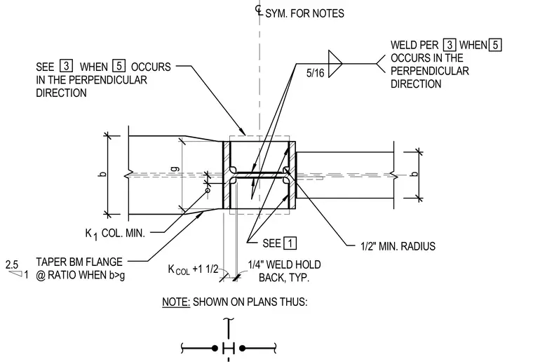
Continuity plates are detailed at the top flange of a steel beam framing into a column with dimensional criteria based on flange width and column properties. A one-quarter inch weld holdback is specified typically, alongside a five-sixteenth inch fillet weld and a one-half inch minimum radius taper on the beam flange when the flange width exceeds the gauge dimension. Additional notes govern conditions when perpendicular directions occur, requiring specific weld applications per drawing references.
1 2.5 K COL. MIN. 1 SEE 1/2" MIN. RADIUS TAPER BM FLANGE @ RATIO WHEN b>g WELD PER WHEN OCCURS IN THE PERPENDICULAR DIRECTION SYM. FOR NOTES SEE WHEN OCCURS IN THE PERPENDICULAR DIRECTION 1' - 2 5/16" b 1 1/2" BACK, TYP. 1/4" WELD HOLD 8 7/16" b K +1 1/2 g COL NOTE: SHOWN ON PLANS THUS: 1 3 5 3 5 5/16
Members view this detail in full resolution, download the CAD files (SVG, PDF), and can adapt it in the built-in CAD editor — export DXF, DWG, or PDF.
Start membership