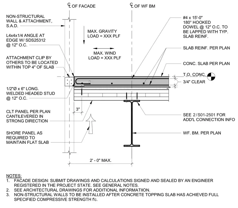
A cross-laminated timber panel is supported by a wide-flange steel beam with an integrated concrete topping slab. The cross-laminated timber panel cantilevers in its strong direction and is shored as required to maintain a flat slab condition. A wide-flange steel beam sits beneath the assembly, connected per plan with additional information referenced on sheet S01-2501. The concrete topping slab is reinforced with number 4 hooked dowels at 12 inches on center lapped with typical slab reinforcement, maintaining a 3/4 inch clear cover. At the slab edge, an L4x4x1/4 angle is fastened with self-drilling screws at 12 inches on center, accommodating a non-structural wall and attachment. A half-inch diameter by 6-inch long welded headed stud is spaced at 12 inches on center, and an attachment clip by others is located within the top 4 inches of the slab.
CONC. SLAB PER PLAN T.O. CONC. 2' - 0" MAX. 3" SEE FOR ADD'L CONNECTION INFO / 2 S01-2501 WF. BM. PER PLAN #4 x 15'-0" 180° HOOKED DOWEL @ 12" O.C. TO BE LAPPED WITH TYP. SLAB REINF. SLAB REINF. PER PLAN 3/4" CLEAR CL OF WF BM CL OF FACADE SHORE PANEL AS REQUIRED TO MAINTAIN FLAT SLAB CLT PANEL PER PLAN CANTILEVERED IN STRONG DIRECTION 1/2"Ø x 6" LONG. WELDED HEADED STUD @ 12" O.C. ATTACHMENT CLIP BY OTHERS TO BE LOCATED WITHIN TOP 4" OF SLAB L4x4x1/4 ANGLE AT EDGE W/ SDS25312 @ 12" O.C. NON-STRUCTURAL WALL & ATTACHMENT, S.A.D. NOTES: 1. FACADE DESIGN: SUBMIT DRAWINGS AND CALCULATIONS SIGNED AND SEALED BY AN ENGINEER REGISTERED IN THE PROJECT STATE. SEE GENERAL NOTES. 2. SEE ARCHITECTURAL DRAWINGS FOR ADDITIONAL INFORMATIION. 3. NON-STRUCTURAL WALLS TO BE INSTALLED AFTER CONCRETE TOPPING SLAB HAS ACHIEVED FULL SPECIFIED COMPRESSIVE STRENGTH f'c. MAX. GRAVITY LOAD = XXX PLF MAX. WIND LOAD = XXX PLF
Members view this detail in full resolution, download the CAD files (SVG, PDF), and can adapt it in the built-in CAD editor — export DXF, DWG, or PDF.
Start membership