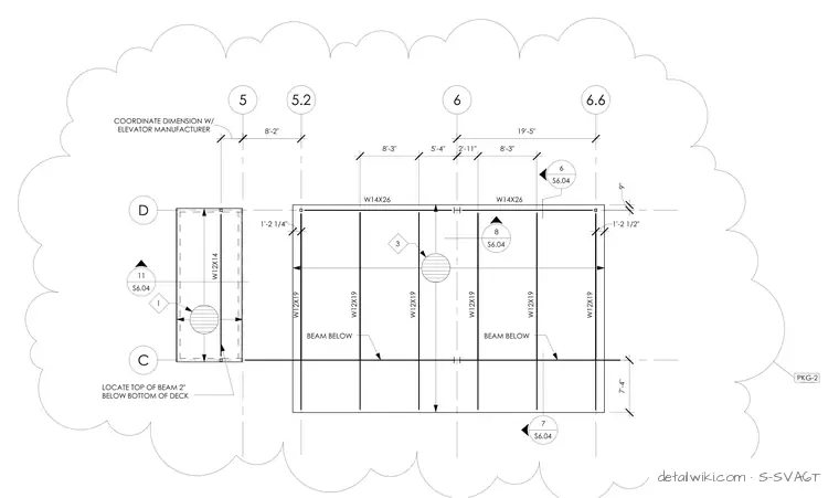
The drawing details a steel framing plan layout featuring W14X26 and W12X19 wide flange steel beams, grid lines, dimensions, and beam elevations. It also includes callout bubbles referencing other structural details and notes regarding beam placement relative to the deck and elevator coordination.
Text on the drawing
C D 5 6 6.6 W12X19 W12X19 W12X19 W12X19 W12X19 W14X26 W14X26 BEAM BELOW BEAM BELOW W12X14 3 1 ELEVATOR MANUFACTURER COORDINATE DIMENSION W/ LOCATE TOP OF BEAM 2" BELOW BOTTOM OF DECK 19'-5" 2'-11" 8'-3" 8 S6.04 11 S6.04 5.2 8'-2" 8'-3" 5'-4" W12X19 6 S6.04 7 S6.04 1'-2 1/2" 1'-2 1/4" 9" 7'-4" PKG-2
Members view this detail in full resolution, download the CAD files (SVG, PDF), and open any detail in the built-in CAD editor to edit and export DXF or DWG.
Sign in to subscribe