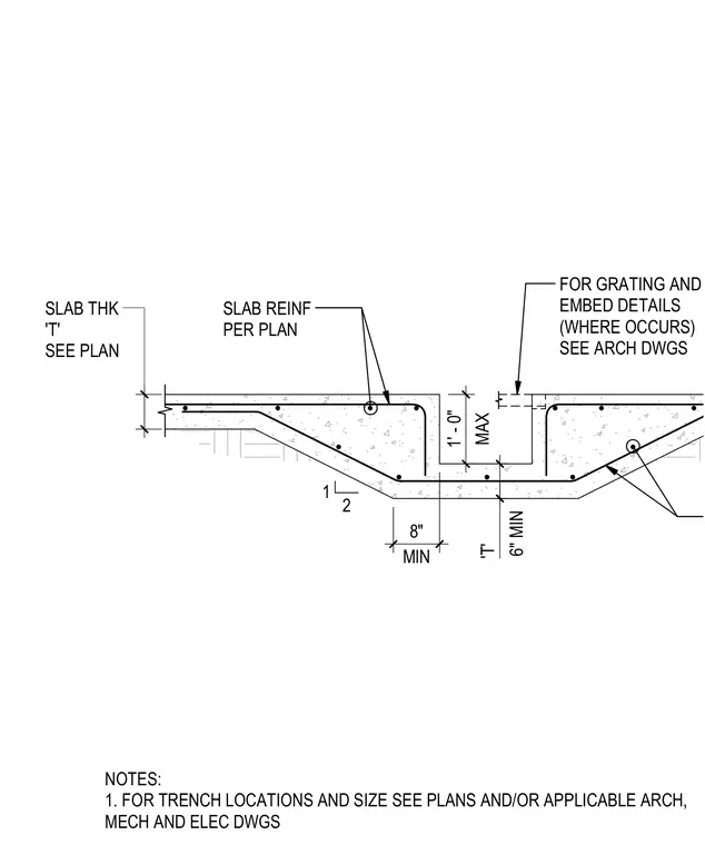
A concrete trench is formed directly within a slab on grade, featuring a maximum depth of one foot and an eight-inch minimum bottom width. The slab thickness T and slab reinforcement are provided per plan, with trench locations and sizes coordinated across architectural, mechanical, and electrical drawings. Grating and embed details are located where required by architectural drawings. The trench invert and side slopes maintain specific minimum thicknesses relative to the overall slab dimension T.
SLAB THK 'T' SEE PLAN 6" MAX 1' - 0" 'T' 6" MIN FOR GRATING AND EMBED DETAILS (WHERE OCCURS) SEE ARCH DWGS SLAB REINF PER PLAN NOTES: 1. FOR TRENCH LOCATIONS AND SIZE SEE PLANS AND/OR APPLICABLE ARCH, MECH AND ELEC DWGS MIN 8" 2 1
Members view this detail in full resolution, download the CAD files (SVG, PDF), and can adapt it in the built-in CAD editor — export DXF, DWG, or PDF.
Start membership