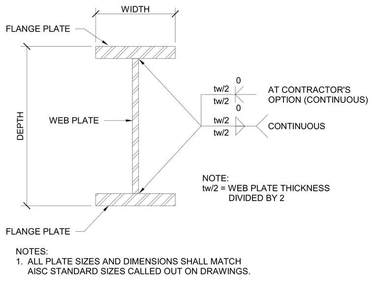
A structural steel welding diagram details the assembly of flange plates and a web plate matching American Institute of Steel Construction standard sizes. The profile dimensions include overall depth and width, with web plate thickness divided by two designated for specific weld configurations. Continuous welds are specified at the plate junctions, with optional configurations provided for the contractor. All plate sizes and dimensions conform to the standard callouts on the structural drawings.
AT CONTRACTOR'S OPTION (CONTINUOUS) 0 0 NOTES: 1. ALL PLATE SIZES AND DIMENSIONS SHALL MATCH AISC STANDARD SIZES CALLED OUT ON DRAWINGS. WEB PLATE FLANGE PLATE FLANGE PLATE NOTE: tw/2 = WEB PLATE THICKNESS DIVIDED BY 2 DEPTH WIDTH tw/2 tw/2 CONTINUOUS tw/2 tw/2
Members view this detail in full resolution, download the CAD files (SVG, PDF), and can adapt it in the built-in CAD editor — export DXF, DWG, or PDF.
Start membership