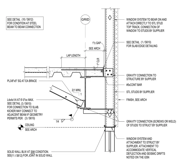
A spandrel bracing connection at a steel beam supports a composite metal deck slab and an exterior steel stud wall assembly. A structural steel angle brace sized L4x4x1/4 is spaced at 6'-0" on center maximum, featuring a 3/8-inch by 5-inch square plate at each brace connected with a 1/4-inch fillet weld. The window system bears directly onto the cold-formed steel stud top track with gravity connections using screws or welds to the primary structure. A continuous reinforcing bar (#5) is incorporated alongside the slab edge detailing, maintaining a 1-inch clearance and a 1-inch approximate gap as coordinated with architectural drawings.
SEE DETAIL FOR CONDITION AT STEEL BEAM TO BEAM CONNECTION / (10 S612) GRID LAP LENGTH 1" CLR SEE ARCH 1"± GAP 2(1 MIN) 1 CEILING SEE ARCH WINDOW SYSTEM TO BEAR ON AND ATTACH DIRECTLY TO STL STUD TOP TRACK, CONNECTION OF WINDOW TO STUDS BY SUPPLIER SEE DETAIL FOR SLAB EDGE DETAILING GRAVITY CONNECTION TO STRUCTURE BY SUPPLIER #5xCONT BAR STL STUDS BY SUPPLIER FINISH, SEE ARCH GRAVITY CONNECTION (SCREWS OR WELD) OF STUDS TO STRUCT BY SUPPLIER WINDOW SYSTEM AND ATTACHMENT TO STRUCT BY SUPPLIER. ATTACHMENT TO ACCOMMODATE VERTICAL DEFLECTION AND SEISMIC DRIFTS NOTED ON THE GSN SOLID WALL BLW AT SIM CONDITION. SEE FOR JOINT IN SOLID WALL / (11 S612) L4x4x1/4 AT 6'-0"oc MAX. SEE DETAIL FOR CONNECTION TO SLAB. KICKER MAY CONNECT TO ADJACENT BEAM IF GEOMETRY PERMITS PER PL3/8"x5" SQ AT EA BRACE 1/4 / (3 S610) / (3 S610) / (1 S610)
Members view this detail in full resolution, download the CAD files (SVG, PDF), and can adapt it in the built-in CAD editor — export DXF, DWG, or PDF.
Start membership