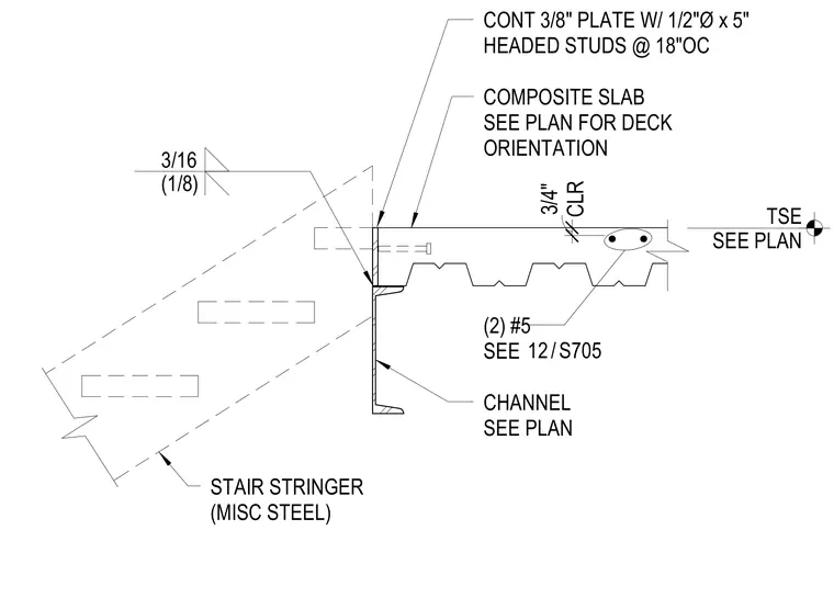
A continuous three-eighths-inch plate welded with a three-sixteenths and one-eighth-inch fillet weld anchors the composite concrete slab edge to a channel section supporting the stair stringer. The composite slab features half-inch diameter by five-inch headed studs spaced at eighteen inches on center, reinforced with two number five bars maintaining a three-quarters-inch clearance. Deck orientation and member sizing are coordinated per the structural framing plans. The top of stair elevation is referenced to the structural drawings.
3/16 (1/8) CONT 3/8" PLATE W/ 1/2"Ø x 5" HEADED STUDS @ 18"OC COMPOSITE SLAB SEE PLAN FOR DECK ORIENTATION CHANNEL SEE PLAN STAIR STRINGER (MISC STEEL) (2) #5 SEE CLR 3/4" SEE PLAN TSE / 12 S705 12 S705
Members view this detail in full resolution, download the CAD files (SVG, PDF), and can adapt it in the built-in CAD editor — export DXF, DWG, or PDF.
Start membership