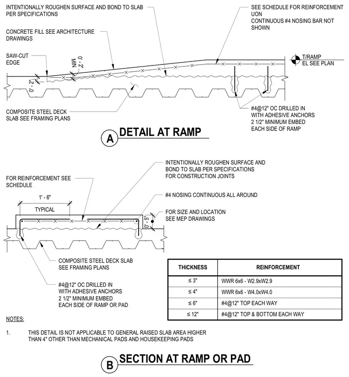
Concrete ramp and housekeeping pad installations on composite steel deck slabs. The assembly features an intentionally roughened concrete surface bonded to the underlying slab per specifications, with saw-cut edges and continuous number 4 nosing bars. Edge anchorage consists of number 4 bars at twelve inches on center installed with adhesive anchors providing a two and a half inch minimum embedment on each side. A reinforcement thickness schedule dictates welded wire reinforcement or number 4 bars top and bottom depending on pad thickness. Notes clarify that the detail excludes general raised slab areas exceeding four inches.
THICKNESS REINFORCEMENT ≤4" ≤6" ≤12" ≤3" WWR 6x6 - W2.9xW2.9 #4@12" TOP EACH WAY #4@12" TOP & BOTTOM EACH WAY CONCRETE FILL SEE ARCHITECTURE DRAWINGS SEE SCHEDULE FOR REINFORCEMENT UON CONTINUOUS #4 NOSING BAR NOT SHOWN COMPOSITE STEEL DECK SLAB SEE FRAMING PLANS INTENTIONALLY ROUGHEN SURFACE AND BOND TO SLAB PER SPECIFICATIONS #4@12" OC DRILLED IN WITH ADHESIVE ANCHORS 2 1/2" MINIMUM EMBED EACH SIDE OF RAMP COMPOSITE STEEL DECK SLAB SEE FRAMING PLANS SAW-CUT EDGE WWR 6x6 - W4.0xW4.0 NOTES: 1. THIS DETAIL IS NOT APPLICABLE TO GENERAL RAISED SLAB AREA HIGHER THAN 4" OTHER THAN MECHANICAL PADS AND HOUSEKEEPING PADS T/RAMP EL SEE PLAN FOR REINFORCEMENT SEE SCHEDULE INTENTIONALLY ROUGHEN SURFACE AND BOND TO SLAB PER SPECIFICATIONS FOR CONSTRUCTION JOINTS FOR SIZE AND LOCATION SEE MEP DRAWINGS #4 NOSING CONTINUOUS ALL AROUND #4@12" OC DRILLED IN WITH ADHESIVE ANCHORS 2 1/2" MINIMUM EMBED EACH SIDE OF RAMP OR PAD 0' - 5" TYPICAL 1' - 6" 0' - 2" MIN 0' - 2" A DETAIL AT RAMP B SECTION AT RAMP OR PAD
Members view this detail in full resolution, download the CAD files (SVG, PDF), and can adapt it in the built-in CAD editor — export DXF, DWG, or PDF.
Start membership