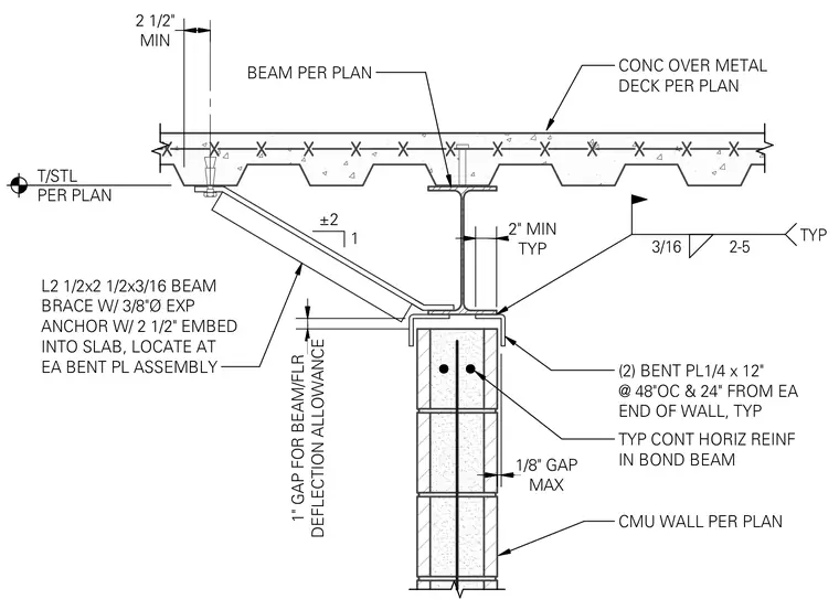
A structural steel beam supporting a concrete over metal deck floor assembly bears atop a concrete masonry unit wall with a continuous horizontal reinforcement bond beam. A bent plate measuring one-quarter inch by twelve inches is located at forty-eight inches on center and twenty-four inches from each end of the wall. An L two-and-a-half by two-and-a-half by three-sixteenths beam brace connects the beam to the slab using a three-eighths-inch diameter expansion anchor with a two-and-a-half-inch embedment, located at each bent plate assembly. A one-inch gap is provided for beam and floor deflection allowance. A two-inch minimum clearance is maintained, with a three-sixteenths-inch fillet weld indicated typically.
BEAM PER PLAN CONC OVER METAL DECK PER PLAN L2 1/2x2 1/2x3/16 BEAM BRACE W/ 3/8"Ø EXP ANCHOR W/ 2 1/2" EMBED INTO SLAB, LOCATE AT EA BENT PL ASSEMBLY (2) BENT PL1/4 x 12" @ 48"OC & 24" FROM EA END OF WALL, TYP TYP CONT HORIZ REINF IN BOND BEAM CMU WALL PER PLAN DEFLECTION ALLOWANCE 1" GAP FOR BEAM/FLR ±2 1 3/16 2-5 TYP TYP 2" MIN MAX 1/8" GAP T/STL PER PLAN MIN 2 1/2" DEFLECTION ALLOWANCE 1" GAP FOR BEAM/FLR TYP 2" MIN MAX 1/8" GAP MIN 2 1/2"
Members view this detail in full resolution, download the CAD files (SVG, PDF), and can adapt it in the built-in CAD editor — export DXF, DWG, or PDF.
Start membership