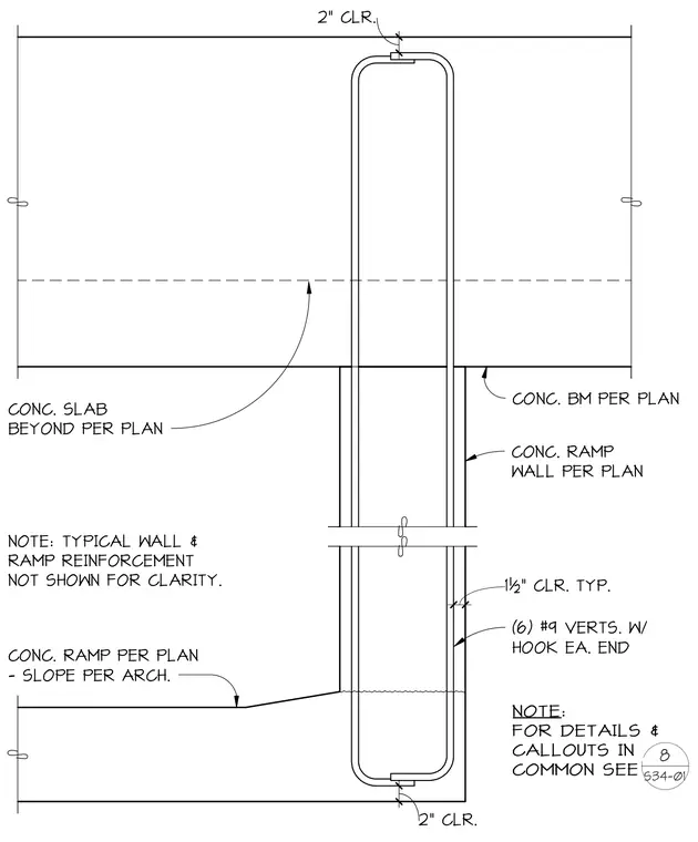
A concrete ramp wall is reinforced with six number nine vertical bars with hooks at each end. A two-inch concrete clearance is maintained at the top and bottom splices, with a one-and-a-half-inch clearance typical along the wall. The assembly interfaces with a concrete beam per plan and a sloping concrete ramp per architectural drawings. A concrete slab is shown beyond per plan. Typical wall and reinforcement details are omitted for clarity.
2" CLR. (6) #9 VERTS. W/ HOOK EA. END CONC. RAMP WALL PER PLAN CONC. RAMP PER PLAN - SLOPE PER ARCH. 2" CLR. CONC. SLAB BEYOND PER PLAN CONC. BM PER PLAN 1½" CLR. TYP. NOTE: TYPICAL WALL & RAMP REINFORCEMENT NOT SHOWN FOR CLARITY. NOTE: FOR DETAILS & CALLOUTS IN COMMON SEE 8 S34-01
Members view this detail in full resolution, download the CAD files (SVG, PDF), and can adapt it in the built-in CAD editor — export DXF, DWG, or PDF.
Start membership