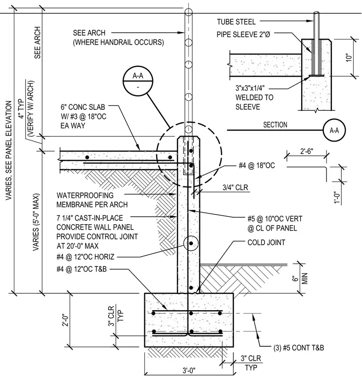
A seven-and-a-quarter-inch cast-in-place concrete wall panel supports a six-inch concrete slab reinforced with number three bars at eighteen inches on center each way. The foundation consists of a continuous footing with three number five continuous top and bottom bars, tied into the wall with number four bars at twelve inches on center top and bottom. A waterproofing membrane is specified per the architect, and a cold joint is detailed above the footing. A two-inch diameter tube steel pipe sleeve is embedded ten inches into the top of the wall panel, welded to a three-by-three-by-one-quarter-inch plate at the base, to accommodate an ADA handrail.
10" TUBE STEEL PIPE SLEEVE 2"Ø 3"x3"x1/4" WELDED TO SLEEVE A-A SECTION 3/4" CLR VARIES, SEE PANEL ELEVATION SEE ARCH VARIES (5'-0" MAX) 2'-0" SEE ARCH (WHERE HANDRAIL OCCURS) 6" CONC SLAB W/ #3 @ 18"OC EA WAY 7 1/4" CAST-IN-PLACE CONCRETE WALL PANEL PROVIDE CONTROL JOINT AT 20'-0" MAX #4 @ 12"OC HORIZ 4" TYP (VERIFY W/ ARCH) 3" CLR TYP 3'-0" 3" CLR TYP (3) #5 CONT T&B #4 @ 12"OC T&B #5 @ 10"OC VERT @ CL OF PANEL #4 @ 18"OC 2'-6" WATERPROOFING MEMBRANE PER ARCH A-A - 1'-0" 6" MIN COLD JOINT
Members view this detail in full resolution, download the CAD files (SVG, PDF), and can adapt it in the built-in CAD editor — export DXF, DWG, or PDF.
Start membership