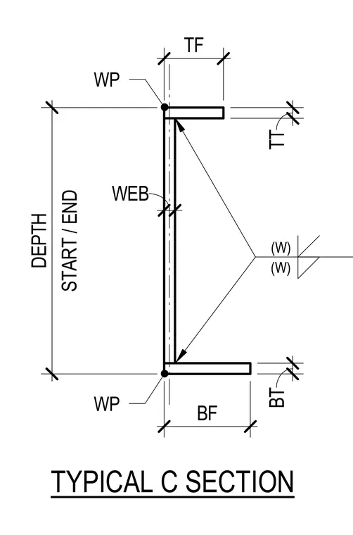
This diagram details the geometric parameters and weld callouts for a typical structural C section. Dimensions include depth, web thickness, top flange width and thickness, and bottom flange width and thickness. Work points define the reference locations at the corners of the web and top flange. Weld symbols indicate the connection criteria along the internal flange-to-web intersections.
Members view this detail in full resolution, download the CAD files (SVG, PDF), and can adapt it in the built-in CAD editor — export DXF, DWG, or PDF.
Start membership