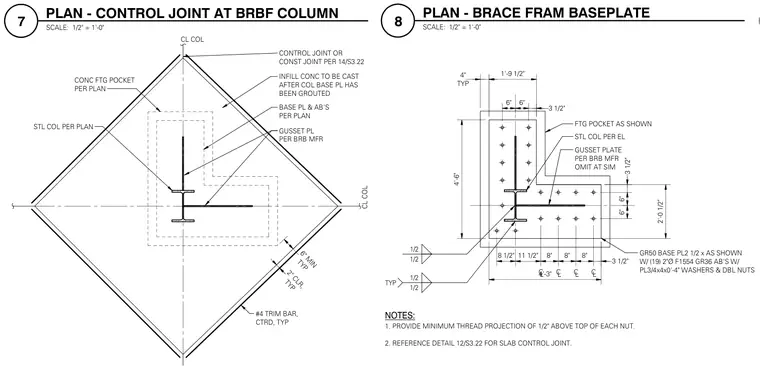
Two plan views show the structural steel column and baseplate assembly seated within a concrete footing pocket. The column features gusset plates sized per the buckling-restrained brace manufacturer and a Grade 50 base plate measuring 2-1/2 inches thick, secured with nineteen 2-inch diameter F1554 Grade 36 anchor bolts with 3/4-inch by 4-inch by 0'-4" washers and double nuts. Infill concrete is designated to be cast after the column base plate has been grouted. Perimeter control joints or construction joints are detailed with number 4 trim bars centered with a 2-inch clearance and a 6-inch minimum typical spacing.
4'-6" 1'-9 1/2" 2'-0 1/2" 4'-3" C L C L C L C L 8 1/2" 11 1/2" 8" 8" 8" 3 1/2" 3 1/2" 6" 6" 6" 6" 3 1/2" TYP 4" GUSSET PLATE PER BRB MFR OMIT AT SIM GR50 BASE PL2 1/2 x AS SHOWN W/ (19) 2"Ø F1554 GR36 AB'S W/ PL3/4x4x0'-4" WASHERS & DBL NUTS STL COL PER EL FTG POCKET AS SHOWN 1/2 1/2 1/2 1/2 TYP NOTES: 1. PROVIDE MINIMUM THREAD PROJECTION OF 1/2" ABOVE TOP OF EACH NUT. 2. REFERENCE DETAIL 12/S3.22 FOR SLAB CONTROL JOINT. CL COL CL COL CONC FTG POCKET PER PLAN STL COL PER PLAN CONTROL JOINT OR CONST JOINT PER 14/S3.22 INFILL CONC TO BE CAST AFTER COL BASE PL HAS BEEN GROUTED GUSSET PL PER BRB MFR BASE PL & AB'S PER PLAN TYP 6" MIN TYP 2" CLR, #4 TRIM BAR, CTRD, TYP SCALE: 1/2" = 1'-0" 8 PLAN - BRACE FRAM BASEPLATE SCALE: 1/2" = 1'-0" 7 PLAN - CONTROL JOINT AT BRBF COLUMN
Members view this detail in full resolution, download the CAD files (SVG, PDF), and can adapt it in the built-in CAD editor — export DXF, DWG, or PDF.
Start membership