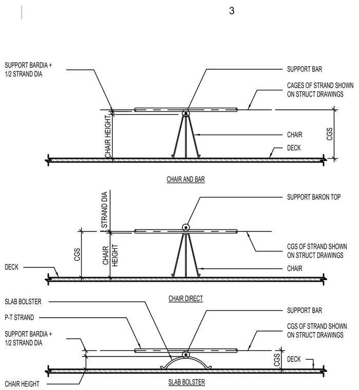
Post-tensioning tendon support assemblies utilize wire chairs and slab bolsters resting directly on the structural deck to maintain precise center of gravity of strand elevations. The chair and bar configuration uses a support bar positioned at the top of a wire chair, supporting cages of strand according to structural drawings with a calculated chair height equal to the center of gravity of strand minus the sum of the support bar diameter and half the strand diameter. The chair direct configuration places the support bar directly atop the apex of the chair. The slab bolster configuration uses a continuous formed wire bolster supporting the post-tensioning strand and support bar above the deck.
CAGES OF STRAND SHOWN ON STRUCT DRAWINGS SUPPORT BARON TOP CGS OF STRAND SHOWN ON STRUCT DRAWINGS CHAIR AND BAR CHAIR DIRECT DECK DECK DECK CGS OF STRAND SHOWN ON STRUCT DRAWINGS P-T STRAND SLAB BOLSTER CHAIR CHAIR SUPPORT BAR SUPPORT BAR SLAB BOLSTER SUPPORT BARDIA + 1/2 STRAND DIA CHAIR HEIGHT SUPPORT BARDIA + 1/2 STRAND DIA CGS CGS CGS CHAIR HEIGHT 1_ 2 STRAND DIA CHAIR HEIGHT 3
Members view this detail in full resolution, download the CAD files (SVG, PDF), and can adapt it in the built-in CAD editor — export DXF, DWG, or PDF.
Start membership