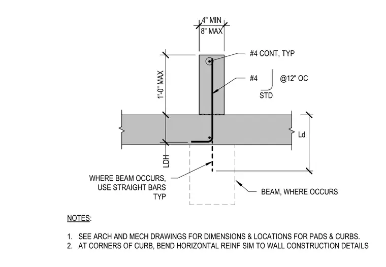
A concrete equipment curb features a four-inch minimum to eight-inch maximum width and a one-foot-zero-inch maximum height above the supporting concrete slab. The curb is reinforced with a continuous number four bar at the top and number four vertical hooked reinforcing bars spaced at twelve inches on center. Straight bars are used where a beam occurs beneath the slab. The underlying concrete beam is indicated with dashed lines where applicable.
WHERE BEAM OCCURS, USE STRAIGHT BARS TYP NOTES: 1. SEE ARCH AND MECH DRAWINGS FOR DIMENSIONS & LOCATIONS FOR PADS & CURBS. 2. AT CORNERS OF CURB, BEND HORIZONTAL REINF SIM TO WALL CONSTRUCTION DETAILS 1'-0" MAX 8" MAX 4" MIN #4 CONT, TYP #4 @12" OC STD LDH Ld BEAM, WHERE OCCURS
Members view this detail in full resolution, download the CAD files (SVG, PDF), and can adapt it in the built-in CAD editor — export DXF, DWG, or PDF.
Start membership