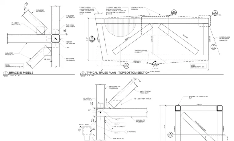
Structural steel truss construction utilizes hollow structural section members and structural angles. The assembly features HSS 6x6x1/4 chords connected to L6x6x3/8 diagonal web members and bracing angles through gusset plates. Exposed surfaces of the truss are covered with 20-gauge B-deck attached to supports with number 10 screws spaced at 6 inches on center. Connection plates measuring 1/2 inch by 4 inches by 4 inches attach with fillet welds featuring two-inch returns. The fabricator must coordinate the truss taper with the radius of the blade sign per sheet S4.10.
4' - 0" HSS PER TYP TRUSS PLAN, TYP L6x6x3/8 L6x6x3/8, AS OCCURS L6x6x3/8 L6x6x3/8 4 S5.55 ANGLE PER TRUSS ELEV ANGLE PER TRUSS ELEV PL & CONN PER 11/S5.55 MAX 1/2" ANGLE PER TRUSS ELEV ANGLE PER TRUSS ELEV PL & CONN PER 17/S5.55 HSS PER TRUSS PLAN TYP 1 1/2" WP NOTE: ANGLES INVERTED @ SIM 1/2" MAX NOTE: BOTTOM PLAN, SIM 20 S5.55 14 S5.55 13 S5.55 L6x6x3/8 HSS 6x6x1/4 HSS 6x6x1/4 L6x6x3/8 L6x6x3/8 S5.55 12 (2) EQ SPACES ~ 10' - 0" 4' - 0" S5.55 18 SIM DIAGONAL WEB MEMBER PER ELEVATION L6x6x3/8 L6x6x3/8 S5.55 11 COVER ALL EXPOSED SURFACES OF TRUSS w/ 20GA B-DECK. ATTACH TO SUPPORTS w/ #10 SCREWS @ 6" O.C. * FABRICATOR TO COORDINATE TRUSS TAPER w/ RADIUS OF BLADE SIGN PER S4.10 DIAGONAL BRACE PER ELEV DIAGONAL BRACE PER ELEV 1 1/2" WP ANGLE PER TYP TRUSS ELEV HSS PER TYP TRUSS PLAN PL & CONN PER 18/S5.55 1/2" MAX ANGLE PER TYP TRUSS ELEV PL & CONN PER 17/S5.55 MAX 1/2" MAX 1/2" COL PER PLAN PL 1/2 x 4 x 0'-4" PL 1/2 x REQ'D 4" TYP 1/4" TYP 1/4" 5/16 2" RETURNS 5/16 1/4 1 1/2" = 1'-0" S5.55 1 BRACE @ MIDDLE 1" = 1'-0" S5.55 2 TYPICAL TRUSS PLAN - TOP/BOTTOM SECTION
Members view this detail in full resolution, download the CAD files (SVG, PDF), and can adapt it in the built-in CAD editor — export DXF, DWG, or PDF.
Start membership