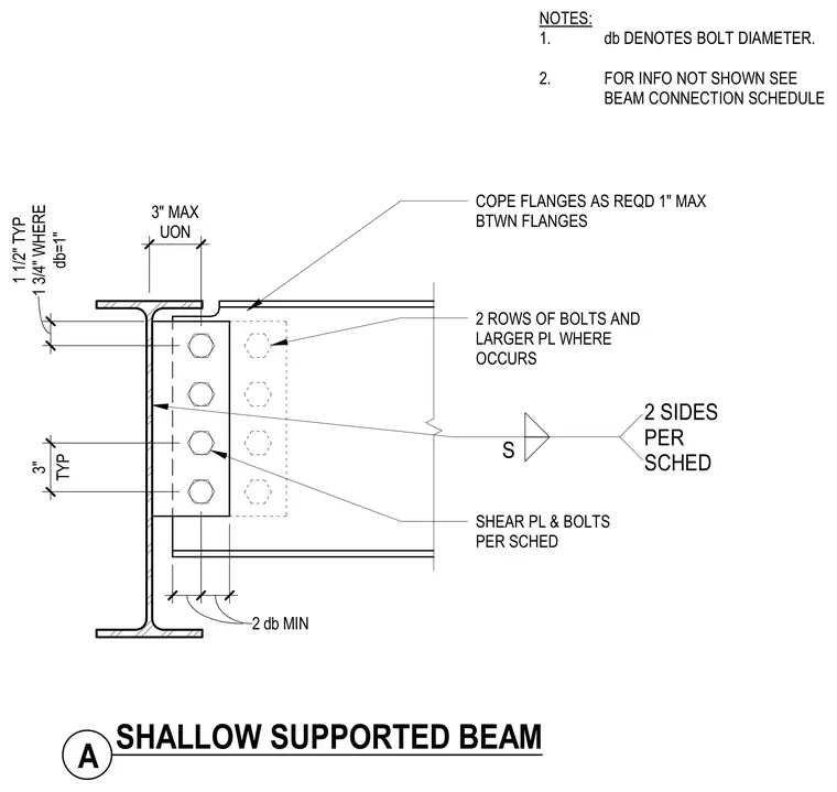
A shallow supported steel beam connects to a supporting member web using a shear plate and bolts sized per schedule. The supported beam flanges are coped as required with a maximum one-inch clearance between the flanges and the support. Two rows of bolts and a larger plate are used where required. Bolt diameter is one inch minimum with standard edge distances and spacings. Additional information is referenced in the beam connection schedule.
COPE FLANGES AS REQD 1" MAX BTWN FLANGES 2 ROWS OF BOLTS AND LARGER PL WHERE OCCURS SHEAR PL & BOLTS PER SCHED 3" MAX UON TYP 3" 2 db MIN db=1" 1 1/2" TYP 1 3/4" WHERE NOTES: 1. db DENOTES BOLT DIAMETER. 2. FOR INFO NOT SHOWN SEE BEAM CONNECTION SCHEDULE A SHALLOW SUPPORTED BEAM S 2 SIDES PER SCHED
Members view this detail in full resolution, download the CAD files (SVG, PDF), and can adapt it in the built-in CAD editor — export DXF, DWG, or PDF.
Start membership