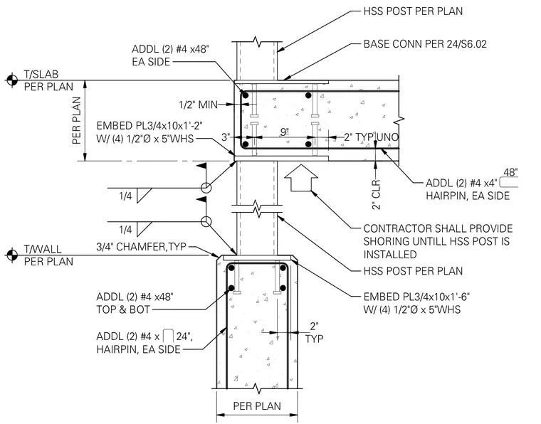
An HSS post spans between a concrete wall and a supported concrete slab, anchored by embedded steel plates with welded headed studs. The upper connection utilizes an embed plate measuring three-quarters of an inch by ten inches by one foot two inches, welded with quarter-inch fillet welds and reinforced with additional number four hairpins on each side. The lower concrete wall features a similar embed plate measuring three-quarters of an inch by ten inches by one-foot six inches with a three-quarter-inch typical chamfer and reinforcing hairpins at the top and bottom. The contractor must provide shoring until the HSS post is installed. Clearances include two inches of concrete cover and a half-inch minimum spacing.
2" CLR T/SLAB PER PLAN T/WALL PER PLAN PER PLAN HSS POST PER PLAN BASE CONN PER 24/S6.02 ADDL (2) #4 x4" HAIRPIN, EA SIDE 48" ADDL (2) #4 x48" EA SIDE EMBED PL3/4x10x1'-2" W/ (4) 1/2"Ø x 5"WHS 1/4 1/4 CONTRACTOR SHALL PROVIDE SHORING UNTILL HSS POST IS INSTALLED HSS POST PER PLAN EMBED PL3/4x10x1'-6" W/ (4) 1/2"Ø x 5"WHS 3/4" CHAMFER,TYP ADDL (2) #4 x48" TOP & BOT ADDL (2) #4 x 24", HAIRPIN, EA SIDE TYP 2" PER PLAN 3" 9" 2" TYP UNO 1/2" MIN
Members view this detail in full resolution, download the CAD files (SVG, PDF), and can adapt it in the built-in CAD editor — export DXF, DWG, or PDF.
Start membership