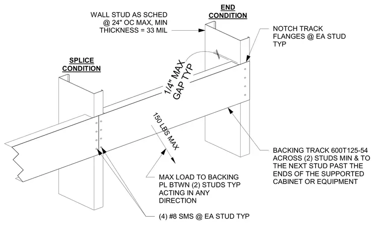
A 600T125-54 backing track spans horizontally across at least two wall studs and extends to the next stud past the ends of any supported cabinet or equipment. Wall studs are spaced at a maximum of 24 inches on center with a minimum thickness of 33 mil. Track flanges are notched at each typical stud location with a maximum gap of 1/4 inch. The splice condition is secured with four number 8 sheet metal screws at each typical stud. This assembly supports a maximum load of 150 pounds between two studs acting in any direction.
150 LBS MAX MAX LOAD TO BACKING PL BTWN (2) STUDS TYP ACTING IN ANY DIRECTION BACKING TRACK 600T125-54 ACROSS (2) STUDS MIN & TO THE NEXT STUD PAST THE ENDS OF THE SUPPORTED CABINET OR EQUIPMENT END CONDITION SPLICE CONDITION (4) #8 SMS @ EA STUD TYP GAP TYP 1/4" MAX WALL STUD AS SCHED @ 24" OC MAX, MIN THICKNESS = 33 MIL NOTCH TRACK FLANGES @ EA STUD TYP
Members view this detail in full resolution, download the CAD files (SVG, PDF), and can adapt it in the built-in CAD editor — export DXF, DWG, or PDF.
Start membership