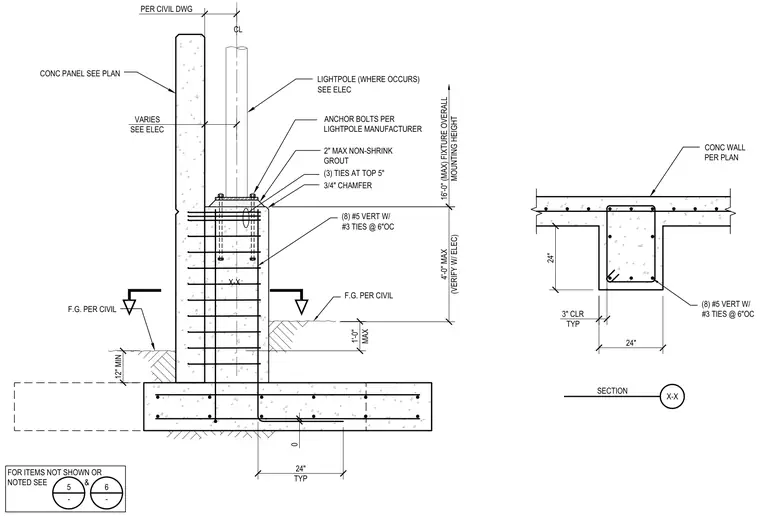
A cast-in-place concrete foundation and wall assembly supports a light pole with anchor bolts provided by the light pole manufacturer over a maximum two-inch non-shrink grout layer. The concrete pier features a 3/4-inch chamfer at the top and is reinforced with eight number 5 vertical bars and number 3 ties at six inches on center, including three ties at the top five inches. The finish grade is coordinated per civil drawings with a 12-inch minimum embedment depth and a maximum four-foot offset verified with electrical plans. A section view X-X details the 24-inch concrete wall and pier configuration with three inches of typical concrete clearance.
4'-0" MAX (VERIFY W/ ELEC) LIGHTPOLE (WHERE OCCURS) SEE ELEC F.G. PER CIVIL (3) TIES AT TOP 5" ANCHOR BOLTS PER LIGHTPOLE MANUFACTURER 3/4" CHAMFER 2" MAX NON-SHRINK GROUT (8) #5 VERT W/ #3 TIES @ 6"OC X-X 16'-0" (MAX) FIXTURE OVERALL MOUNTING HEIGHT CONC WALL PER PLAN 24" 24" (8) #5 VERT W/ #3 TIES @ 6"OC 3" CLR TYP X-X SECTION CONC PANEL SEE PLAN VARIES SEE ELEC 0 CL PER CIVIL DWG 24" TYP F.G. PER CIVIL 1'-0" MAX 12" MIN FOR ITEMS NOT SHOWN OR NOTED SEE & 5 - 6 -
Members view this detail in full resolution, download the CAD files (SVG, PDF), and can adapt it in the built-in CAD editor — export DXF, DWG, or PDF.
Start membership