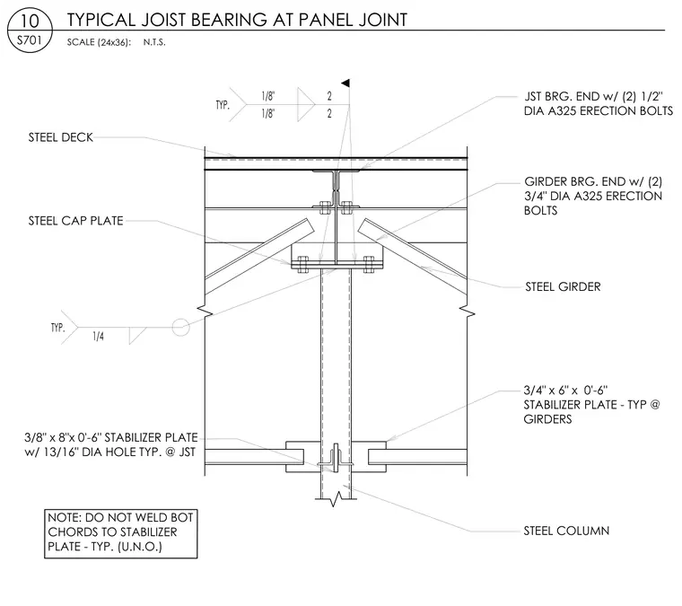
This structural steel detail shows a typical joist bearing connection at a panel joint, supported by a steel girder and a steel column. The steel girder bearing end is secured to a steel cap plate using two 1/2-inch diameter ASTM A325 erection bolts, while the joist bearing end is connected with two 3/4-inch diameter ASTM A325 erection bolts. Stabilizer plates measuring 3/4 inch by 6 inches by 0 feet 6 inches are provided typically at the girders, along with 3/8-inch by 8-inch by 0-feet-6-inch stabilizer plates featuring 13/16-inch diameter holes at the joists. A fillet weld with a 1/4-inch size is specified typically at the connection. The bottom chords of the joists are left unwelded to the stabilizer plate unless otherwise noted.
GIRDER BRG. END w/ (2) 3/4" DIA A325 ERECTION BOLTS 3/4" x 6" x 0'-6" STABILIZER PLATE - TYP @ GIRDERS STEEL GIRDER JST BRG. END w/ (2) 1/2" DIA A325 ERECTION BOLTS STEEL COLUMN NOTE: DO NOT WELD BOT CHORDS TO STABILIZER PLATE - TYP. (U.N.O.) TYP. 1/4 3/8" x 8"x 0'-6" STABILIZER PLATE w/ 13/16" DIA HOLE TYP. @ JST STEEL CAP PLATE TYP. 1/8" 1/8" 2 2 STEEL DECK SCALE ( ): 24x36 10 S701 TYPICAL JOIST BEARING AT PANEL JOINT N.T.S.
Members view this detail in full resolution, download the CAD files (SVG, PDF), and can adapt it in the built-in CAD editor — export DXF, DWG, or PDF.
Start membership