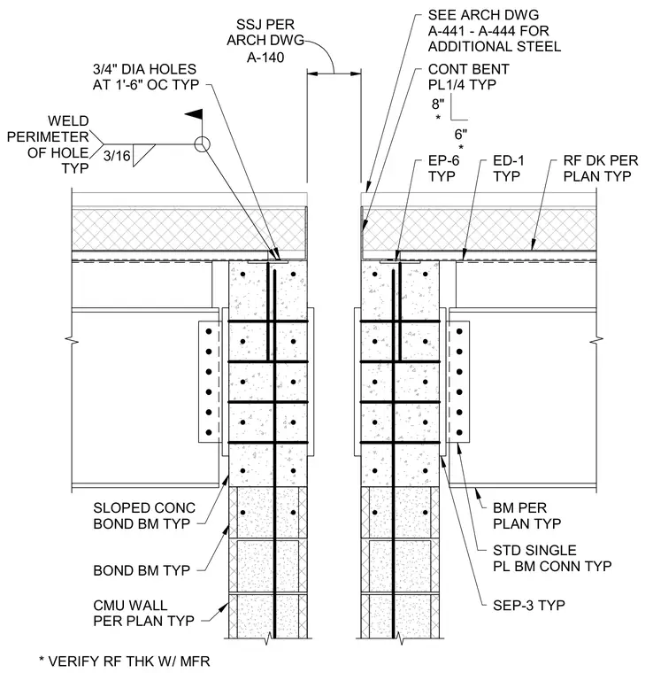
A roof expansion joint condition occurs between concrete masonry unit walls topped with sloped concrete bond beams. A continuous bent plate measuring 1/4 inch thick by 8 inches by 6 inches is anchored with three-quarter-inch diameter holes spaced at 1 foot 6 inches on center, secured with a 3/16-inch perimeter fillet weld around the holes. Standard single plate beam connections tie structural steel beams per plan into the masonry assembly. Roof deck and additional steel framing are coordinated per architectural drawings.
CONT BENT PL1/4 TYP 8" * 6" * EP-6 TYP RF DK PER PLAN TYP CMU WALL PER PLAN TYP BOND BM TYP SLOPED CONC BOND BM TYP SEE ARCH DWG A-441 - A-444 FOR ADDITIONAL STEEL ED-1 TYP BM PER PLAN TYP STD SINGLE PL BM CONN TYP SEP-3 TYP A-140 SSJ PER ARCH DWG * VERIFY RF THK W/ MFR 3/16 WELD PERIMETER OF HOLE TYP 3/4" DIA HOLES AT 1'-6" OC TYP
Members view this detail in full resolution, download the CAD files (SVG, PDF), and can adapt it in the built-in CAD editor — export DXF, DWG, or PDF.
Start membership