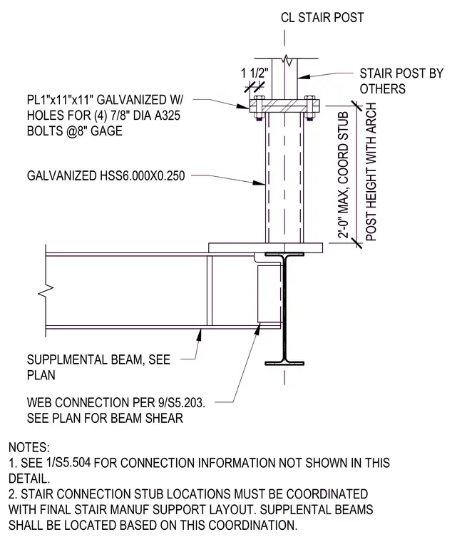
A galvanized hollow structural section measuring six inches by a quarter-inch thick forms a stair connection stub mounted to a supplemental steel beam sized per plan. A one-inch thick by eleven-inch square galvanized plate with four seven-eighth-inch diameter A325 bolts at eight-inch gauge connects the stair post by others to the stub. The post height is coordinated with the architectural drawings to a maximum of two feet. A web connection per detail 9/S5.203 secures the supplemental beam to its support.
WEB CONNECTION PER 9/S5.203. SEE PLAN FOR BEAM SHEAR NOTES: 1. SEE FOR CONNECTION INFORMATION NOT SHOWN IN THIS DETAIL. 2. STAIR CONNECTION STUB LOCATIONS MUST BE COORDINATED WITH FINAL STAIR MANUF SUPPORT LAYOUT. SUPPLENTAL BEAMS SHALL BE LOCATED BASED ON THIS COORDINATION. SUPPLMENTAL BEAM, SEE PLAN PL1"x11"x11" GALVANIZED W/ HOLES FOR (4) 7/8" DIA A325 BOLTS @8" GAGE STAIR POST BY OTHERS POST HEIGHT WITH ARCH 2'-0" MAX, COORD STUB CL STAIR POST GALVANIZED HSS6.000X0.250 1 1/2" 1/S5.504 WEB CONNECTION PER 9/S5.203. SEE PLAN FOR BEAM SHEAR NOTES: 1. SEE FOR CONNECTION INFORMATION NOT SHOWN IN THIS DETAIL. 2. STAIR CONNECTION STUB LOCATIONS MUST BE COORDINATED WITH FINAL STAIR MANUF SUPPORT LAYOUT. SUPPLENTAL BEAMS SHALL BE LOCATED BASED ON THIS COORDINATION. SUPPLMENTAL BEAM, SEE PLAN PL1"x11"x11" GALVANIZED W/ HOLES FOR (4) 7/8" DIA A325 BOLTS @8" GAGE STAIR POST BY OTHERS POST HEIGHT WITH ARCH 2'-0" MAX, COORD STUB CL STAIR POST GALVANIZED HSS6.000X0.250 1 1/2" 1/S5.504
Members view this detail in full resolution, download the CAD files (SVG, PDF), and can adapt it in the built-in CAD editor — export DXF, DWG, or PDF.
Start membership