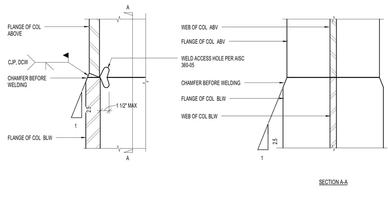
A splice connection joins columns of differing profiles, connecting the flange of the column above to the flange of the column below. The connection features a chamfered transition profile with a two-to-one slope ratio on the column flange below. A complete joint penetration weld with a backing bar or weld contour is specified at the flange junction. A one-and-a-half-inch maximum weld access hole is provided at the web intersection in accordance with AISC 360 standards. Section A-A provides both flange and web alignment perspectives for the vertical steel members.
1 2.5 SECTION A-A FLANGE OF COL ABOVE CHAMFER BEFORE WELDING FLANGE OF COL BLW WEB OF COL BLW FLANGE OF COL BLW CHAMFER BEFORE WELDING FLANGE OF COL ABV WEB OF COL ABV 1 2.5 CJP, DCW 1 1/2" MAX WELD ACCESS HOLE PER AISC 360-05 A A
Members view this detail in full resolution, download the CAD files (SVG, PDF), and can adapt it in the built-in CAD editor — export DXF, DWG, or PDF.
Start membership