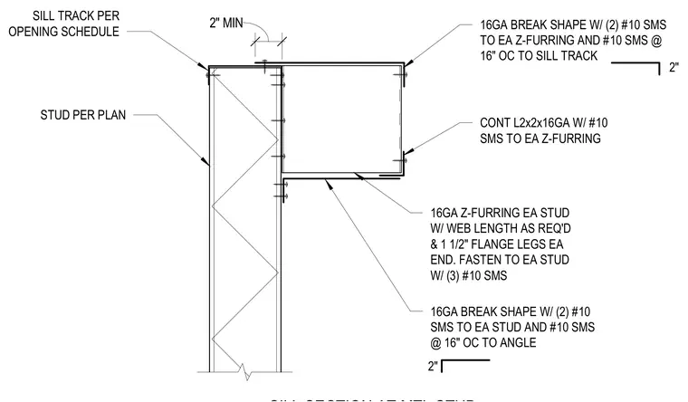
The assembly features a sill track sized per the opening schedule supported by metal studs per plan. A sixteen-gauge Z-furring with required web length and one and one-half inch flange legs attaches to each stud using three number ten sheet metal screws. A continuous two-by-two sixteen-gauge angle connects to each Z-furring with number ten sheet metal screws. A sixteen-gauge break shape fastens to each Z-furring with two number ten sheet metal screws and to the sill track with number ten sheet metal screws at sixteen inches on center. An additional sixteen-gauge break shape secures to each stud with two number ten sheet metal screws and to the angle with number ten sheet metal screws at sixteen inches on center, maintaining a two-inch minimum clearance.
SILL TRACK PER OPENING SCHEDULE STUD PER PLAN 16GA Z-FURRING EA STUD W/ WEB LENGTH AS REQ'D & 1 1/2" FLANGE LEGS EA END. FASTEN TO EA STUD W/ (3) #10 SMS CONT L2x2x16GA W/ #10 SMS TO EA Z-FURRING 16GA BREAK SHAPE W/ (2) #10 SMS TO EA Z-FURRING AND #10 SMS @ 16" OC TO SILL TRACK 2" MIN 2" 16GA BREAK SHAPE W/ (2) #10 SMS TO EA STUD AND #10 SMS @ 16" OC TO ANGLE 2"
Members view this detail in full resolution, download the CAD files (SVG, PDF), and can adapt it in the built-in CAD editor — export DXF, DWG, or PDF.
Start membership