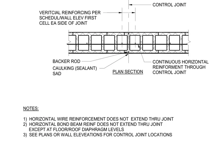
A continuous control joint in a concrete masonry wall features vertical reinforcing placed in the first cell on each side of the joint. The joint opening is sealed with caulking and supported by a backer rod. Horizontal wire reinforcement and bond beam reinforcement do not extend through the joint, except at floor and roof diaphragm levels where continuous horizontal reinforcement is maintained.
NOTES: 1) HORIZONTAL WIRE REINFORCEMENT DOES NOT EXTEND THRU JOINT 2) HORIZONTAL BOND BEAM REINF DOES NOT EXTEND THRU JOINT EXCEPT AT FLOOR/ROOF DIAPHRAGM LEVELS 3) SEE PLANS OR WALL ELEVEATIONS FOR CONTROL JOINT LOCATIONS CAULKING (SEALANT) SAD BACKER ROD VERITCIAL REINFORCING PER SCHEDUL/WALL ELEV FIRST CELL EA SIDE OF JOINT CONTROL JOINT PLAN SECTION CONTINUOUS HORIZONTAL REINFORMENT THROUGH CONTROL JOINT
Members view this detail in full resolution, download the CAD files (SVG, PDF), and can adapt it in the built-in CAD editor — export DXF, DWG, or PDF.
Start membership