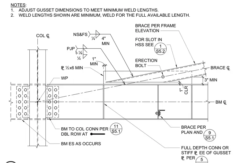
A gusset plate connection joins a hollow structural section brace to a supporting steel beam and column. The steel beam frames into the column flange using a double row bolted connection, while an erection bolt temporarily secures the diagonal brace over the beam top flange. A half-inch minimum plate connects the brace, utilizing partial joint penetration and quarter-inch fillet welds on near and far sides with specified minimum clearances. Gusset dimensions are adjusted to meet minimum weld lengths, and full depth connections or stiffener plates are provided as required. A one-inch clearance is maintained between the framing elements.
3" MIN ERECTION BOLT BRACE ¢ BM ¢ BRACE PER FRAME ELEVATION FOR SLOT IN HSS SEE 1 S5.2 WP BM TO COL CONN PER DBL ROW AT BM ES AS OCCURS 11 S5.1 COL ¢ NOTES: 1. ADJUST GUSSET DIMENSIONS TO MEET MINIMUM WELD LENGTHS. 2. WELD LENGTHS SHOWN ARE MINIMUM, WELD FOR THE FULL AVAILABLE LENGTH. BRACE PER PLAN AND 9 S5.1 FULL DEPTH CONN OR STIFF £ EE OF GUSSET £ PER 5 £Ïx6 MIN t-É PJP Ë 4" MIN NS&FS Ë CLR 1" MIN 1"
Members view this detail in full resolution, download the CAD files (SVG, PDF), and can adapt it in the built-in CAD editor — export DXF, DWG, or PDF.
Start membership