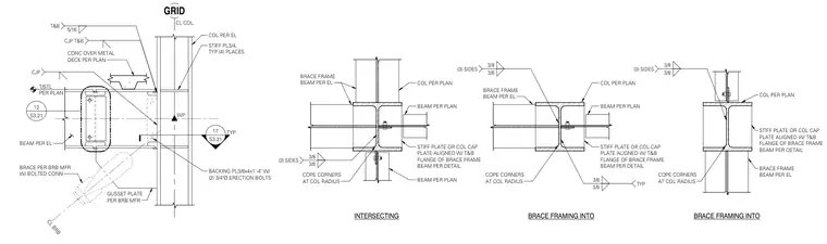
Column stiffener plate configurations and connection details for braced frame systems occur at structural steel columns. Three-quarter inch thick stiffener plates are provided in four locations, aligned with the top and bottom flanges of the brace frame beam, and welded with three-eighths inch fillets on three sides with corners coped at the column radius. A backing plate measuring three-eighths by four inches by one foot four inches is secured with two three-quarters inch diameter erection bolts. Brace frames frame into intersecting columns with associated beam connections, gusset plates, and buckling-restrained braces per manufacturer requirements.
3/8 3/8 (3) SIDES COPE CORNERS AT COL RADIUS BEAM PER PLAN STIFF PLATE OR COL CAP PLATE ALIGNED W/ T&B FLANGE OF BRACE FRAME BEAM PER DETAIL BEAM PER PLAN COL PER PLAN BRACE FRAME BEAM PER EL 3/8 3/8 (3) SIDES COPE CORNERS AT COL RADIUS STIFF PLATE OR COL CAP PLATE ALIGNED W/ T&B FLANGE OF BRACE FRAME BEAM PER DETAIL BEAM PER PLAN COL PER PLAN BRACE FRAME BEAM PER EL 3/8 3/8 TYP BRACE FRAMING INTO INTERSECTING COL PER PLAN STIFF PLATE OR COL CAP PLATE ALIGNED W/ T&B FLANGE OF BRACE FRAME BEAM PER DETAIL BRACE FRAME BEAM PER EL COPE CORNERS AT COL RADIUS 3/8 3/8 (3) SIDES BRACE FRAMING INTO GRID CL COL COL PER EL STIFF PL3/4, TYP (4) PLACES BACKING PL3/8x4x1'-4" W/ (2) 3/4"Ø ERECTION BOLTS WP CONC OVER METAL DECK PER PLAN GUSSET PLATE PER BRB MFR BRACE PER BRB MFR W/ BOLTED CONN CL BRB BEAM PER EL T/STL PER PLAN 5/16 T&B CJP T&B CJP TYP S3.21 12 S3.21 17
Members view this detail in full resolution, download the CAD files (SVG, PDF), and can adapt it in the built-in CAD editor — export DXF, DWG, or PDF.
Start membership