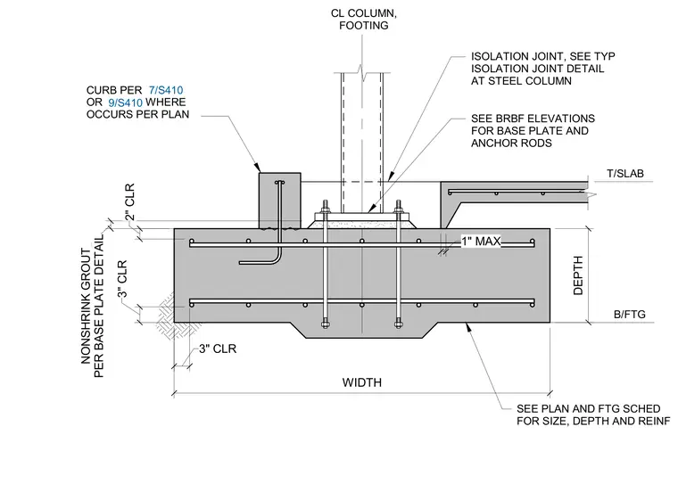
A steel column connects to a reinforced concrete footing via a base plate and anchor rods set over a nonshrink grout layer. The concrete footing incorporates top and bottom reinforcing steel with specified cover clearances and a stepped bottom profile. An adjacent concrete slab interfaces with the column base through an isolation joint, and a reinforced concrete curb is detailed at the perimeter where indicated per plan.
B/FTG T/SLAB CL COLUMN, FOOTING SEE PLAN AND FTG SCHED FOR SIZE, DEPTH AND REINF DEPTH SEE BRBF ELEVATIONS FOR BASE PLATE AND ANCHOR RODS 3" CLR WIDTH 3" CLR 1" MAX ISOLATION JOINT, SEE TYP ISOLATION JOINT DETAIL AT STEEL COLUMN PER BASE PLATE DETAIL NONSHRINK GROUT 2" CLR CURB PER OR WHERE OCCURS PER PLAN 7/S410 9/S410
Members view this detail in full resolution, download the CAD files (SVG, PDF), and can adapt it in the built-in CAD editor — export DXF, DWG, or PDF.
Start membership