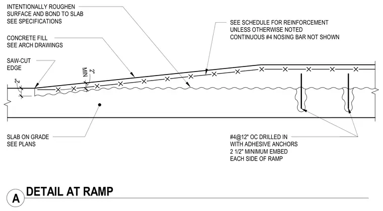
A concrete fill ramp is placed over an intentionally roughened slab on grade with the surface bonded per specifications. A continuous number four nosing bar runs through the assembly. The ramp terminates at a saw-cut edge with a two-inch minimum thickness transition. Number four reinforcing bars spaced at twelve inches on center are drilled in with adhesive anchors maintaining a two and one-half inch minimum embedment on each side of the ramp.
CONCRETE FILL SEE ARCH DRAWINGS SEE SCHEDULE FOR REINFORCEMENT UNLESS OTHERWISE NOTED CONTINUOUS #4 NOSING BAR NOT SHOWN SLAB ON GRADE SEE PLANS INTENTIONALLY ROUGHEN SURFACE AND BOND TO SLAB SEE SPECIFICATIONS #4@12" OC DRILLED IN WITH ADHESIVE ANCHORS 2 1/2" MINIMUM EMBED EACH SIDE OF RAMP SAW-CUT EDGE 2" MIN 2" A DETAIL AT RAMP
Members view this detail in full resolution, download the CAD files (SVG, PDF), and can adapt it in the built-in CAD editor — export DXF, DWG, or PDF.
Start membership