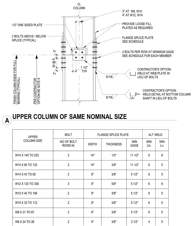
A column splice connection for wide-flange steel columns of the same nominal size utilizes bolted or alternative welded flange and web connections. The assembly includes flange splice plates with dimensions and thicknesses governed by a companion schedule, alongside a one-half-inch one-sided plate and loose fill plates provided as required. Two bolts are specified above and below the splice per row at minimum gage, with column ends finished for full bearing. Contractors are given the option to substitute five-sixteenth-inch fillet welds at the web plate and bottom column shaft in lieu of bolts.
3" AT W8, W10 4" AT W12, W14 PROVIDE LOOSE FILL PLATES AS REQUIRED FLANGE SPLICE PLATE SEE SCHEDULE 2 BOLTS ABOVE / BELOW SPLICE (TYPICAL) FINISH COLUMN ENDS FOR FULL BEARING (TYPICAL) PER CONTRACTOR OPTION RE NOTE 9 NO OF BOLT ROWS Nr WIDTH THICKNESS W14 X 145 TO 233 W14 X 90 TO 132 W14 X 43 TO 82 W12 X 120 TO 336 W12 X 40 TO 106 W10 X 33 TO 112 UPPER COLUMN SIZE 2 BOLTS PER ROW AT MINIMUM GAGE SEE SCHEDULE FOR EACH MEMBER CONTRACTOR'S OPTION: WELD DETAIL AT BOTTOM COLUMN SHAFT IN LIEU OF BOLTS Lv 1 Lh 1 CL COLUMN 1/2" ONE SIDED PLATE FLANGE SPLICE PLATE ALT WELD 2" 3 63/64" CONTRACTOR'S OPTION: WELD AT WEB PLATE IN LIEU OF BOLTS 5/16 TYP 1 1/2" 5/16 MIN GAGE W8 X 31 TO 67 W8 X 24 TO 28 2" Nr @ S A UPPER COLUMN OF SAME NOMINAL SIZE MIN Lh 1 6 6 6 6 6 6 6 4 MIN Lv 1 8 5 5 8 5 5 5 5 3 2 2 3 2 2 2 2 14" 14" 8" 8" 8" 8" 8" 6" 1/2" 3/8" 3/8" 5/8" 3/8" 3/8" 3/8" 3/8" 11 1/2" 11 1/2" 5 1/2" 5 1/2" 5 1/2" 5 1/2" 5 1/2" 3 1/2" BOLT
Members view this detail in full resolution, download the CAD files (SVG, PDF), and can adapt it in the built-in CAD editor — export DXF, DWG, or PDF.
Start membership