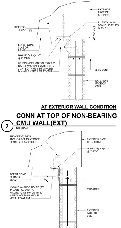
Lateral connection at the top of a non-bearing exterior concrete masonry unit wall to an overhead concrete slab or beam soffit. The assembly incorporates a 5/16 inch by 8 inch by 14 inch steel plate embedded with two 3/4 inch diameter by 6 inch studs at 2 feet 8 inches on center, welded with a 1/4 inch fillet weld on three sides. A continuous 6x4x5/16 inch structural steel angle, 1 foot 0 inches long at 2 feet 8 inches on center, attaches horizontally with a vertical leg secured to the CMU wall using two 5/8 inch diameter anchor bolts at an 8 inch gauge, complete with 5/16 inch plate washers measuring 2-3/4 inches square through 1-5/8 inch diameter holes. Two continuous number 5 reinforcing bars run horizontally within the top courses of the masonry wall, maintaining a 1/2 inch clearance at the exterior face of the building.
(2)#5 CONT L6x4x5/16(LLV)x1'-0" @ 2'-8"OC EXTERIOR FACE OF CMU PROVIDE (2) 5/8"Ø ANCHOR BOLTS AT CONC SLAB OR BEAM SOFFIT (2) 5/8"Ø ANCHOR BOLTS (AT 8" GAGE) W/ 5/16" PL WASHERS x 2-3/4" SQ THRU 1-5/8"Ø HOLES IN ANGLE VERT LEG AT CMU SOFFIT CONC SLAB OR BEAM EXTERIOR FACE OF BUILDING 2" AT EXTERIOR WALL CONDITION (2)#5 CONT L6x4x5/16(LLV)x1'-0" @ 2'-8"OC EXTERIOR FACE OF CMU PL 5/16"8x14 W/ 2-3/4"Øx6" STUDS @ 2'-8" OC (2) 5/8"Ø ANCHOR BOLTS (AT 8" GAGE) W/ 5/16" PL WASHERS x 2-3/4" SQ THRU 1-5/8"Ø HOLES IN ANGLE VERT LEG AT CMU SOFFIT CONC SLAB OR BEAM EXTERIOR FACE OF BUILDING 1/4 3 SIDES TYP 1/2" CLR NO SCALE CONN AT TOP OF NON-BEARING CMU WALL(EXT) 2
Members view this detail in full resolution, download the CAD files (SVG, PDF), and can adapt it in the built-in CAD editor — export DXF, DWG, or PDF.
Start membership