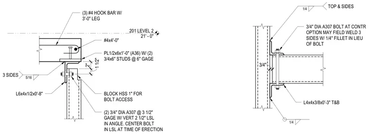
The connection assembly at an elevator frame interfaces a concrete slab edge with structural steel framing. The concrete slab incorporates three number four hook bars with three-foot legs and an embedded half-inch by six-inch by one-foot plate made of A36 steel with two three-quarter-inch by six-inch studs at a six-inch gauge. An angle section is welded with a five-sixteenth-inch fillet weld on three sides and connected to a hollow structural section with two three-quarter-inch diameter A307 bolts at a three-and-a-half-inch gauge with a vertical two-and-a-half-inch slotted hole in the angle, centered at the time of erection. The hollow structural section is blocked by one inch to provide bolt access. An alternate detail view shows a horizontal member secured with three-quarter-inch diameter A307 bolts, with a contractor option to field weld three sides with a quarter-inch fillet in lieu of bolts at the top and sides, using four-by-four-by-three-eighths-inch angles at zero feet three inches top and bottom.
3/4" 3/4" DIA A307 BOLT AT CONTR OPTION MAY FIELD WELD 3 SIDES W/ 1/4" FILLET IN LIEU OF BOLT TOP & SIDES 1/4 L4x4x3/8x0'-3" T&B 1/4 201 LEVEL 2 21' - 0" 2" 1 1/2" BLOCK HSS 1" FOR BOLT ACCESS PL1/2x6x1'-0" (A36) W/ (2) 3/4x6" STUDS @ 6" GAGE #4x4'-0" (3) #4 HOOK BAR W/ 3'-0" LEG (2) 3/4" DIA A307 @ 3 1/2" GAGE W/ VERT 2 1/2" LSL IN ANGLE. CENTER BOLT IN LSL AT TIME OF ERECTION L6x4x1/2x0'-8" 3 SIDES 5/16
Members view this detail in full resolution, download the CAD files (SVG, PDF), and can adapt it in the built-in CAD editor — export DXF, DWG, or PDF.
Start membership