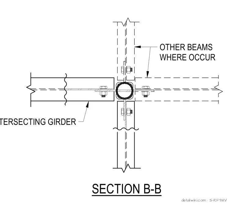
The drawing illustrates a structural section view (Section B-B) detailing the connection between intersecting girders and surrounding framing beams. Steel structural members are bolted together using connection plates and fasteners, providing structural continuity at intersections. Dashed lines indicate the positioning of additional beams where they occur in the framing layout.
Text on the drawing
OTHER BEAMS WHERE OCCUR INTERSECTING GIRDER SECTION B-B
Members view this detail in full resolution, download the CAD files (SVG, PDF), and open any detail in the built-in CAD editor to edit and export DXF or DWG.
Sign in to subscribe