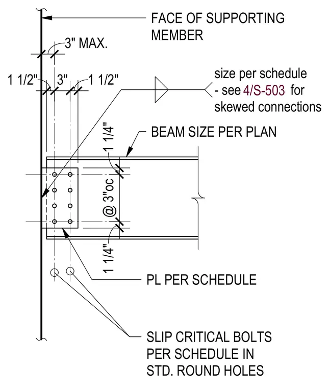
A structural steel beam connects to the face of a supporting member using a plate sized per schedule and slip-critical bolts installed in standard round holes. The bolt pattern uses three-inch spacing on center with edge and spacing dimensions including one and one-half inch and one and one-quarter inch clearances. A note directs to sheet 4/S-503 for skewed connections.
BEAM SIZE PER PLAN PL PER SCHEDULE FACE OF SUPPORTING MEMBER SLIP CRITICAL BOLTS PER SCHEDULE IN STD. ROUND HOLES size per schedule - see for skewed connections 1 1/2" 3" 1 1/2" 3" MAX. 1 1/4" @ 3"oc 1 1/4" 4/S-503
Members view this detail in full resolution, download the CAD files (SVG, PDF), and can adapt it in the built-in CAD editor — export DXF, DWG, or PDF.
Start membership