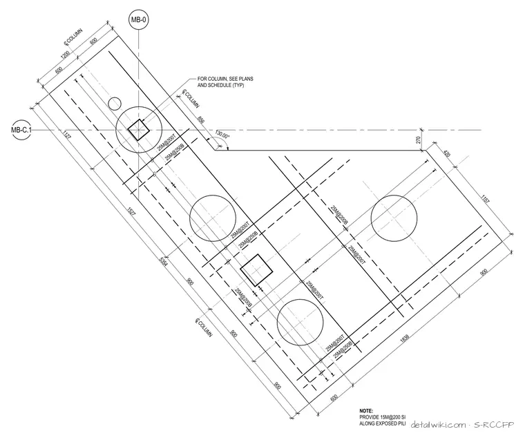
The drawing presents a plan view of a multi-column reinforced concrete pile cap detailing the arrangement of reinforcing steel bars and column centerlines. Key components include top and bottom reinforcing bars designated as 25M@200T and 25M@250B, pile locations, and column connection points. Dimension lines and grid lines define the spatial layout and positioning for structural engineering and construction.
Text on the drawing
C L COLUMN C L COLUMN CLCOLUMN 25M@200B 25M@200B 25M@200T 25M@200T 25M@200T 25M@200T 25M@250B 25M@250B 25M@250B 25M@200T MB-0 MB-C.1 600 600 1127 1527 900 900 900 600 1838 900 1200 130.00° 5354 NOTE: PROVIDE 15M@200 SIDE-FACE REINFORCEMENT ALONG EXPOSED PILE CAP EDGES. FOR COLUMN, SEE PLANS AND SCHEDULE (TYP) 1157 420 856 270
Members view this detail in full resolution, download the CAD files (SVG, PDF), and open any detail in the built-in CAD editor to edit and export DXF or DWG.
Sign in to subscribe