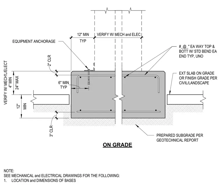
A typical concrete equipment pad is set on a prepared subgrade per the geotechnical report, adjacent to an exterior slab on grade or finish grade. The concrete pad features top and bottom reinforcing steel running each way with standard bends at each end, maintaining specified clearances. Equipment anchorage bolts are embedded into the top of the concrete base. Dimensions, locations, and heights of the bases must be verified with mechanical and electrical drawings.
MIN 12" 24" MAX VERIFY W/ MECH'L/ELECT 4" MIN #_@_" EA WAY TOP & BOTT W/ STD BEND EA END TYP, UNO ON GRADE EXT SLAB ON GRADE OR FINISH GRADE PER CIVIL/LANDSCAPE NOTE: SEE MECHANICAL and ELECTRICAL DRAWINGS FOR THE FOLLOWING: 1. LOCATION and DIMENSIONS OF BASES 3" CLR 2" CLR VERIFY W/ MECH and ELEC TYP 12" MIN TYP 6" MIN EQUIPMENT ANCHORAGE PREPARED SUBGRADE PER GEOTECHNICAL REPORT
Members view this detail in full resolution, download the CAD files (SVG, PDF), and can adapt it in the built-in CAD editor — export DXF, DWG, or PDF.
Start membership