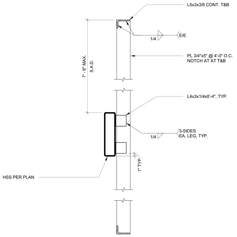
Continuous top and bottom angles secure the channel glass assembly, welded with a quarter-inch fillet weld on three sides of each leg. Intermediate three-quarter by five-inch steel plates are spaced at four feet on center with notched top and bottom connections. Short structural angles measuring four by three by one-quarter inches connect back to the hollow structural section beam sized per plan. A maximum span of seven feet six inches is maintained between supports with a one-inch typical clearance.
1" TYP. S.A.D. 7' - 6" MAX. HSS PER PLAN L4x3x1/4x0'-4", TYP. PL 3/4"x5" @ 4'-0" O.C. NOTCH AT AT T&B L5x3x3/8 CONT. T&B E/E 1/4 3-SIDES EA. LEG, TYP. 1/4
Members view this detail in full resolution, download the CAD files (SVG, PDF), and can adapt it in the built-in CAD editor — export DXF, DWG, or PDF.
Start membership