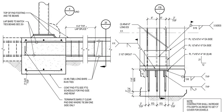
A concrete wall panel holdown connection is anchored to a continuous pad footing and tie beam. The assembly incorporates a base plate measuring 1 inch by 16 inches by 1 foot 4 inches welded with three number 9 bars, eight feet long, running each side. Additional side plates measuring 1/2 inch by 10 inches by 1 foot 4 inches and 1/2 inch by 8 inches by 1 foot 0 inches are attached with specified fillet welds on three sides. Three inch concrete clearance is maintained throughout, with a two and a half inch grout layer beneath the steel base assembly. The tie beam features four number 6 top and bottom longitudinal bars enclosed in number 3 ties, with a five foot typical lap splice and one foot nine inch minimum embedment. Dowels and reinforcing bars are detailed to ensure proper load transfer between the precast or tilt-up panel and the foundation.
TERMINATE BARS 3" CLEAR PAD END WHERE TIE BM ONE SIDE ONLY CONT PAD FTG SEE FTG SCHEDULE FOR PAD SIZE AND REINF 3" CLR TYP LAP BARS TO MATCH TIES BEAMS SEE 20/- (4) #6 (T&B) LONG BARS IN #3 TIES 20 - 8 - UNO 5'-0" TYP LAP SPLICE TOP OF PAD FOOTING AND TIE BEAMS 1'-9" MIN 3" CLR 2 1/2" GROUT F.F. (3) #9x8'-0" LONG ES PL 1"x16"x1'-4" W/ (9) #6 PL 1/2"x8"x1'-0" EA SIDE PL 1/2"x10"x1'-4" EA SIDE 17B - P.P. 2" TYP 3/8 TYP 5/16 3 SIDES 21 12 2" TYP EQ EQ 6" 6" NOTE: CONTRACTOR SHALL INCREASE FTG DEPTH AS REQD TO GET 3" COVER FOR DOWELS 2" TYP 5 TYP 4"
Members view this detail in full resolution, download the CAD files (SVG, PDF), and can adapt it in the built-in CAD editor — export DXF, DWG, or PDF.
Start membership