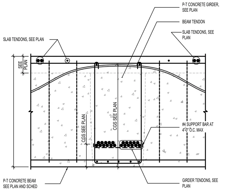
A post-tensioned concrete beam frames into a post-tensioned concrete girder with designated slab and beam tendons positioned per structural plans and schedules. Girder tendons run continuously through the section with center-of-gravity profiles detailed per plan. A number 4 support bar is spaced at four feet zero inches on center maximum to support the tendon profile. Slab tendons are anchored across the top and sides of the assembly with spacing and center-of-gravity coordinates referenced on plan.
SLAB TENDONS, SEE PLAN BEAM TENDON SLAB TENDONS, SEE PLAN P-T CONCRETE BEAM SEE PLAN AND SCHED P-T CONCRETE GIRDER, SEE PLAN #4 SUPPORT BAR AT 4'-0" O.C. MAX GIRDER TENDONS, SEE PLAN SEE PLAN CGS SEE PLAN CGS SEE PLAN
Members view this detail in full resolution, download the CAD files (SVG, PDF), and can adapt it in the built-in CAD editor — export DXF, DWG, or PDF.
Start membership